INTRODUCTION
4.1. The ICAO term ‘helideck’ comprises helicopter landing sites on both ships and floating/fixed off-shore structures. Australian Defence assets only include ships, with no floating/fixed off-shore structures. As such Defence uses the term ‘shipborne heliport’ to identify ‘helideck’ as a landing site on ships.
4.2. This chapter details the design requirements for shipborne heliports. These shipborne heliports are used solely for rotary wing operations (including tilt-rotor). For the design requirements for land based heliports, and integrating rotary wing operations into fixed-wing aerodromes, refer to Chapters 1, 2 and 3 of this section.
4.3. Shipborne heliports range from ships with single-spot flight decks, through to large multi-spot ships with extensive movement areas, helicopter runways and multiple combinations of approach paths and operations. The intent of this chapter is to provide design requirements for all types of shipborne heliports, in a form that is scalable depending on the capability requirement.
4.4. The definition of shipborne heliports does not include ship areas used for utility operations (i.e. VERTREP, Transfer). However as these utility operations are often conducted from the area of the shipborne heliport (i.e the flight deck), design requirements for utility operations are specified in so far as they can affect function of the shipborne heliport (e.g. flight deck markings).
4.5. The shipborne heliport design requirements and the associated variations and supplementations defined by the Authority for each of the identified design elements detailed in Chapter 1 Annex A of this section, are described below.
4.6. This Chapter derived all its Safety of Flight (SoF) requirements from DEF(AUST)5000 Vol 11 Pt03 Iss02 (Nov 17). This chapter takes precedence over Vol 11 Part 3 for all SoF requirements. All personnel/ships safety and capability requirements for a shipborne heliport are kept retained in the unaltered DEF(AUST)5000 Vol 11 publications with sponsorship transferred to DGEng-N. DEF(AUST)5000 is the whole of ship Maritime Materiel Requirement Set (MMRS). These requirements will transition into the Australian Naval Classification Framework (ANCF) in due course.
4.7. The DASA should be consulted to resolve any ambiguity, or if further clarification is required in implementing these SoF requirements. Any concerns with requirements coverage, precedence or other issues in relation to SoF shipborne heliport requirements are to be addressed to DASA. Other requirements to DGEng-N.
HAZARD INFORMATION
4.8. Aviation operations at sea are hazardous. They are a ‘whole of ship evolution’ where the equipment are subject to temperature extremes, high seas and wind states, rotor downwash, high salt-laden environment, black noise levels, radiation from electromagnetic sources along with exposure and close proximity to potentially lethal equipment (weapons, ordnance, rotor blades, exhaust effluxes, high-pressure gas and fluid systems). These operations may be conducted through both day and night, including via NVD and in extreme conditions on wet and moving decks, and within confined spaces. These operations require personnel to be routinely closer to the operating aircraft than may be the case in a shore-based operations.
4.9. It is essential that aviation evolutions are conducted effectively, efficiently and safely to minimise the hazard to the ship, ships personnel and its effect on unrelated ships activities. Aviation operations create extra hazards for the ship, as any accidents endanger the safety of the ship as a whole. An aircraft crash on deck with the related risk of shrapnel damage and an aviation fuel fire could be catastrophic. In times of conflict, the loss of an air asset severely decreases the effectiveness and ability of a ship to carry out its mission to fight and win at sea. Conduct of air operations can affect every department on the ship.
4.10. Shipborne heliport operations experience hazards, additional to those associated with Aerodrome Design elements as defined by DASDRM S6 C1 Annex A. These hazards are associated with the movement of a shipborne heliport (both in location and attitude), communications and situational awareness, which are not covered by an Air Navigation Service Provider as they are for land-based aerodromes. To address these types of hazards, this chapter of DASDRM contains additional requirements for those design elements that are not common to land based aerodromes.
SHIPBORNE HELIPORT DESIGN REQUIREMENTS
Shipborne Heliport Communications
4.11. The various communications networks shall be available at the locations detailed in Table 1.
Table 1 - Communications Networks
| STATION/ | NETWORK | |||||
| USER | UHF Radio | Main Broadcast2 | Flight Deck Broadcast | Helicopter Intercom | Flight Deck Team3 | Phone5 |
| Bridge | T/R 1 | T/R | T/R | T/R | ||
| Ops Room/AC | T/R | T/R | T/R | T/R | ||
| HCO | T/R | R | T/R | T/R | T/R | T/R |
| LSO | T/R | R | T/R | T/R | T/R | T/R |
| FDO | T/R | R | T/R | T/R | T/R | T/R |
| VERTREP CS | T/R | R | T/R | T/R | ||
| Transfer CS | T/R | R | T/R | T/R | ||
| FDM | R 6 | R 6 | T/R 4 | T/R | ||
| Flight Deck Crew | R 6 | R 6 | R | |||
| Helicopter | T/R | |||||
| Flight Deck | R | R | T/R | |||
| Hangar | R | R | T/R | |||
| VERTREP Area | R | |||||
| Transfer Area | R | |||||
| RAST machinery room | R | R | T/R | |||
| Helicopter Firefighting Station | R | R | T/R | |||
| Refuelling stations | R | R | T/R | |||
| Ships Primary Damage Control | R | T/R | ||||
T – Transmit, R- Receive
Note 1. Typically the Bridge does not communicate directly with aircraft.
Note 2. Main Broadcast is broadcast throughout the ship.
Note 3. Flight Deck Team communications should be wireless.
Note 4. For FDM communication on the Helicopter Intercom a wireless headset connection shall be provided.
Note 5. In this table, ship telephone system includes electronic phone and sound-powered phone for redundancy.
Note 6. FDM and FD Crew are unlikely to hear broadcasts with hearing protection donned, however broadcast communications are required when activities are conducted without hearing protection.
4.12. External Radio Communications. The external radio communications detailed in this section shall be provided for all air capable ships to support the coordination of aviation operations at sea. DEF(AUST)5000–Vol 06 Pt 02 Sec 13 provides RAN requirements for radio frequency systems.
4.13. The external radio systems shall be able to communicate with the required aircraft over all ranges required within the Navigation and Tracking aid requirements defined in Table 2 (located at para 4.145).
4.14. UHF Radio. A UHF radio patch shall be provided from the ship's normal UHF transmitter/receiver equipment to the stations indicated at Table 1. A standby UHF radio circuit shall be provided from the ship’s normal UHF transmitter/receiver equipment as back-up to the primary UHF system during flying operations. This circuit shall be immediately available in case of failure of the primary circuit for patching to the same stations.
4.15. Distress Monitoring. A loudspeaker monitoring facility shall be provided for the International UHF Distress Frequency. This shall be patched through from the ship's normal UHF receiver equipment to the Operations Room, Helicopter Control Station (HCS) and Communications Centre (COMCEN) during flying operations.
4.16. Emergency Standby VHF Radio. An emergency standby, battery-powered, portable VHF radio shall be provided on the Bridge during flying operations.
4.17. Search and Rescue Radio Direction Finding. All air capable ships shall be equipped with a Radio Direction Finding set capable of giving homing indication from the standard aircrew search and rescue beacon equipment used in the RAN. The normal frequencies used are 121.5 MHz, 123.1 MHz, 243.0 MHz, 282.8 MHz and 406 MHz.
4.18. Internal Communications. The aviation facilities communications systems shall be common to the ship’s general internal communication systems. Internal communications systems shall comply with DEF(AUST)5000–Vol 06 Pt 06 Sec 01. Facilities shall be provided as specified in the following paragraphs.
4.19. Intercom System. An open–line intercom system exclusively for helicopter operations (designated ‘HELICOPTER INTERCOM’) shall be provided between the stations indicated at Table 1.
The intercom facility shall be combined into the operator’s headset.
4.20. Wire-Free Flight Deck Communications. A wire-free intercom system (designated ‘FLIGHT DECK MARSHALLING’) shall be provided. The system shall comply with Australian standards for hearing protection and shall facilitate reception of communications as per Flight Deck Team at Table 1 through individual headsets. Transmit function shall be restricted to the Helicopter Control Officer (HCO), Flight Deck Marshaller (FDM), Landing Safety Officer (LSO) and Flight Deck Officer (FDO) as applicable. The system shall be EMC compatible, intrinsically safe within the operational environment, NVD compliant as required, and comply with Work Health and Safety standards. Consideration should be given for encryption.
4.21.1. Internal Telephone and Ship’s Service Telephone. Internal Telephone and / or Ship service telephones shall be installed in all aviation-related areas as per Table 1 to provide point to point communications and also conference call facilities. In high noise areas, a flashing light shall be provided to attract attention.
4.21.2 Sound-Powered Telephones. A sound-powered telephone system shall be provided as an alternative or as a backup in emergency situations for the Telephone system between the stations shown in Table 1.
4.22. Broadcast Systems. The following broadcast systems, applicable to aviation operations, shall comply with DEF(AUST)5000 Vol 6 Pt 6 Sec 1 (except for the reference to ABR 5419 is to be replaced with ANP 3300) and the following:
Flight Deck Broadcast (FDB). A broadcast system exclusively for flight deck operations shall be provided as shown in Table 1 with transmit facilities at the HCO, LSO and FDO positions (where applicable).
Main Broadcast (MB). Loudspeakers for the ship’s main broadcast announcements shall be installed at the positions designated in Table 1 with transmit facilities at the Bridge, Operations Room/Aircraft Control (AC) station, HCO, LSO and FDO positions.
Command Request and Approval Systems
4.23. The ship shall provide a system that enables the HCO/LSO/FDO to request approval for aircraft operations, and then for the Commanding Officer to approve (or not approve) the request without dependence on voice communications.
4.24. Captain’s Ready Deck Circuit. A Captain’s Ready Deck Circuit shall be installed between the Bridge and Operations room and the HCO/LSO/FDO (control position), as applicable, to permit the Captain to maintain control over aircraft operations. The Captain’s Ready Deck Circuit shall provide the following facilities:
The HCO/LSO/FDO display/control console shall allow the operator to request clearance/approval for a particular type of operation (covering all operations the ship is capable of performing). The console shall indicate that the clearance has been requested until the Bridge responds with a YES or NO.
The Bridge display/control console shall include an indicator and cancellable audible device to indicate when the HCO/LSO/FDO has requested clearance for a particular type of evolution. The Bridge shall be able to respond with a YES or NO. An indicator light at the HCO/LSO/FDO shall display the selection made by the bridge indicating if the operation has been approved or not approved.
A display/control console shall be integrated into the Helmsman’s control console on the bridge. The display shall be visible to an OOW standing midships of the bridge.
A similar display/control console should be located at the Aircraft Controller (AC) position in the Operations room.
The HCO/LSO/FDO, Bridge Staff and AC shall each have the ability to initiate an emergency wave-off. Initiation of an emergency wave-off shall be indicated to all consoles with a combination of flashing lights and an audible alarm. The audible alarm shall be cancellable for each individual station. The emergency wave-off shall be cancelled by the initiating control station only.
Ship External Lighting
Floodlighting
4.25. Floodlighting shall be aimed to provide the best possible illumination of the deck area while keeping spill over of the flight deck to a minimum. Floodlighting shall avoid shining directly into the cockpit during take-off and landing and when on the flight deck.
Night Vision Device Compatibility
4.26. Lighting of ships certified for night operations (Level I or II) shall comply with DEFSTAN 02-587. The NVD compatibility of lighting systems shall be assessed against the class (or classes) of Night Vision system in use on ADF helicopters.
4.27. Lighting includes aviation-specific lights such as deck wash lights, visual landing aids such as SGSI and HRS, and non-aviation lights visible during launch, recovery, VERTREP and transfer operations (examples include emergency lighting, boat deck lighting, etc).
Closed Circuit TeleVision (CCTV) system
4.28. General. A CCTV system shall provide a video feed of the flight deck to at least the Bridge, AC station in Operations Room, hangar and HCS for any spots that cannot be seen clearly with the naked eye in the intended range of environmental conditions.
4.29. The CCTV system shall enable appropriate actions in the event of an emergency in addition to general situational awareness as a means of reducing risk.
4.30. The CCTV images shall be fed to Damage Control locations and hangar.
4.31. The CCTV system shall provide a video feed of the hangar to provide images to ship Command and Damage Control locations, so that during an incident, the Crash Rescue Fire Fighting (CRFF) team/s and automated fire detection systems can be monitored.
4.32. CCTV Video Recording. The CCTV system shall incorporate a video recording capability with the following features:
All flight deck video cameras shall be recorded concurrently if there is more than one camera.
The video feed to the recorder shall be independent of the selection at any of the displays, i.e. it shall not be possible to inadvertently record a feed other than flight deck cameras.
Flight deck video shall be recorded continuously to ensure video recording is not inadvertently forgotten. If this is not the case, then the video recorder control shall be located in the HCS.
The system shall have a minimum seven-day recording capability.
It shall be possible to quarantine video (so that it cannot be deleted) in the event of an accident or incident.
It shall be possible to copy selected video to other media for further analysis or archiving.
The field of view shall provide coverage of the helicopter final approach path and flight deck area during helicopter operations including land/launch, HIFR, VERTREP and Transfer. The camera shall also have remote zoom/scan facility from the HCS, to provide coverage of the landing area, approach paths and hangars
The camera shall have anti-glare and low light capability down to 0.002 Lux.
The camera shall be sited in a position protected from weather and physical damage and fitted with a remotely operated wash/wipe capability.
Fire Protection
4.33. Aviation Firefighting – Flight Deck. As described within STANAG 7183, occupants of an aircraft subject to fire can’t be expected to survive if exposed for 90 seconds or more. The response and effectiveness of the aviation firefighting system is critical to the rescue of those occupants and wider protection of the vessel and its crew. Therefore, designers shall demonstrate that:
The aviation firefighting system is able to bring the fire under control within one minute (60 seconds) from the incident occurring.
The fire can be contained to enable ‘rescue’ of the occupants to commence as soon as possible after the incident occurring and suppressed for sufficient time to complete the rescue operation.
The fire can be fully extinguished shortly afterwards.
Sufficient extinguishing agent remains to maintain control of the incident, prevent re-ignition (burn back), protect the vessel and ‘cool’ any munitions carried by the aircraft. STANAG 4240 details the testing of munitions subject to aviation fuel fires.
4.34. To demonstrate compliance with the above requirements, the designer shall conduct a Fire Safety Study (FSS) in accordance with DEF(AUST)5000, Volume 7, Part 2 Annex B.
Fire Protection – Foam Properties
4.35. Foam extinguishing agent shall meet the requirements of MIL-F-24385F as detailed in DEF(AUST) 5000, Volume 7, Part 2, Annex K.
4.36. The FSS required in paragraph 4.34 shall demonstrate that the foam meets MIL-F- 24385F requirements.
4.37. Foam Quantities and Application Rates. In determining the foam quantity and application rate to effectively control, contain and extinguish an aviation fuel fire, the dimensions of the largest aircraft that the flight deck is designed to accommodate shall be used to determine the Practical Critical Area (PCA). The method of calculation in STANAG 7183 shall be used to determine PCA.
4.38. For aircraft with external fuel tanks, the width aspect of the PCA does not incorporate the tanks.
4.39. The methodology within DEF(AUST)5000, Volume 7, Part 2, Annex K shall be used to determine the two-dimensional foam quantity requirements in addition to those for the PCA.
4.40. DEF(AUST)5000 Volume 7, Part 2 Annex K shall be used to determine the application rates for foam systems.
4.41. Time from firefighting system activation until correctly proportioned foam is delivered on to the landing area from all Foam Systems shall be documented.
4.42. The FSS required in paragraph 4.34 shall demonstrate how the quantities and application rates were determined for the largest helicopter to be operated, and how they correlate to controlling the fire within one minute, containing the fire, extinguishing the fire and protecting the vessel.
Fire Protection - Remotely Operated Fixed Foam Systems.
4.43. Remotely operated fixed foam firefighting systems shall be installed. In-deck (flush deck) and deck edge sprinklers are the preferred system and shall be designed to meet the requirements in DEF(AUST)5000, Volume 7, Part 2, Annex K.
4.44. Oscillating Foam Monitors are an alternative system, however they shall meet the requirements of DEF(AUST)5000, Volume 7, Part 2, Annex K.
4.45. Fixed foam storage systems, supplying automated fixed foam systems, shall meet the requirements of DEF(AUST)5000 Volume 7, Part 2, Annex K.
4.46. Remotely operated fixed foam systems shall be designed such that the required foam quantity and application rates can still be delivered should part of the system(s) be rendered unusable by the incident occurring. In the case of foam monitors, each monitor shall be able to deliver the required quantity of agent at the appropriate rate should the other(s) become unusable.
4.47. Location of activation points for the remotely operated systems shall be in accordance with DEF(AUST)5000, Volume 7, Part 2, Annex K.
4.48. Remotely operated fixed foam systems shall provide coverage to all areas of the flight deck where the PCA can reside.
4.49. The FSS required in paragraph 4.34 shall demonstrate compliance with the requirements in this section (Fire protection), detailing the system redundancy performance and location of monitors for most effective performance.
Fire Protection – Hand-Held Foam Systems
4.50. Hand-held foam hose lines shall be installed to provide a directed extinguishing agent to the scene of the fire and shall be designed to cover all areas of the flight deck where the PCA can reside.
4.51. Hand-held foam hose lines utilising either fixed proportioning systems or inductors and portable drums of foam shall be provided. The hand-held foam hose lines shall deliver the quantities of foam, at the appropriate application rate, as detailed in DEF(AUST)5000, Volume 7, Part 2, Annex K.
4.52. The location of the foam hose lines shall be designed to afford the best possible protection from damage resulting from the aircraft incident and shall provide full redundancy should other hose lines become unusable.
4.53. Hand-held foam hose lines shall be installed with aspirating foam nozzles.
4.54. Proportioning systems, storage tanks and/or portable drums shall provide sufficient foam agent in accordance with DEF(AUST)5000, Volume 7, Part 2, Annex K requirements.
4.55. The FSS required in paragraph 4.34 shall demonstrate that the design of the foam hand-held hose lines support the remotely operated fixed systems in controlling, containing and extinguishing the fire within the required timeframes, and have the endurance to continue protection of the vessel and ‘cooling’ of munitions.
Fire Protection – Foam Aspiration
4.56. All flight deck AFFF firefighting systems shall correctly aspirate foam.
4.57. In-deck sprinkling systems naturally aspirate the foam agent at discharge. Non-aspirating in-deck nozzles, meeting requirements of DEF(AUST)5000, Volume 7, Part 2, Annex K, are acceptable.
4.58. Hand-held foam hose lines shall be fitted with aspirating nozzles in accordance with the requirements at DEF(AUST)5000, Volume 7, Part 2, Annex K.
4.59. Foam monitor nozzles shall meet the requirements of DEF(AUST)5000, Volume 7, Part 2, Annex K.
4.60. The FSS required in paragraph 4.34 shall demonstrate that the nozzles for handheld lines, in-deck sprinklers and foam monitors aspirate the foam effectively, having taken into consideration environmental effects, such as the strength of the wind across the flight deck, in conditions reflective of aircraft operations, i.e. Ship Helicopter Operating Limits (SHOL).
Fire Protection - Miscellaneous
4.61. Operating Instructions. Operating instructions for all firefighting equipment and systems shall be posted adjacent to the system or equipment.
4.62. To prevent the spread of the fire and reduce effectiveness of the emergency response, fuel (spillage) from the flight deck shall not be able to enter the hangar.
4.63. VERTREP Operating Area. The fixed fire-fighting system (remotely operated and hand held) requirements for air capable ships shall be met for operations to VERTREP operating areas. The FSS required in paragraph 4.34 shall demonstrate how the design of the system(s) reflects the largest aircraft that shall conduct the operation (including largest fuel load), taking into consideration the types of underslung load for the type of vessel.
Aviation System Storage Area
Hangar Doors
4.64. Hangar Door Pressure Tolerance. The hangar door shall be operable (open and close) with winds in any direction up to 60 kts.
4.65. Hangar Door – Requirements when Closed. In the closed position, the hangar door shall:
Prevent any light from being visible from outboard during ’Darken Ship‘ conditions.
Comply with fuel-spill prevention requirements of paragraph 4.62.
4.66. Other Hangar Accesses. In addition to the main hangar door access, there shall be a general access between the flight deck and hangar area. This access shall be provided for normal passage, and may be used for emergency passage as per the requirements of paragraph 4.85 and 4.86. The general access shall be operable from both sides, open onto the flight deck and, when closed, maintain the weather tightness and fire resistance of the hangar area. Provision shall be made at this hatch for blackout curtaining to prevent light from the hangar being shown inadvertently on the flight deck. Access to the interior of the ship from the hangar shall also be available. General access from the flight deck to the interior of the ship shall not be via the hangar/hangars.
4.67. Viewing Port. The hangar general access door, or the immediate surround, shall be fitted with a viewing port, which permits CRFF team in the hangar to observe operations on the flight deck when the hangar door is closed. The viewing port shall:
Meet the requirements of paragraph 4.181.
Be fitted with an integral blackout cover that shall prevent light from spilling onto the flight deck, remain attached when open and closed, and shall be able to be locked in both the open and closed position.
Hangar Internal Lighting
4.68. Hangar internal lighting shall be controlled such that it will automatically switch to night lighting if the hangar door (or other hangar access to the flight deck) is opened while the lights are on.
Flight Operations Area
Clearance Criteria for Landing and Launching Operations
4.69. For a ship to be certified to land and launch a helicopter, certain minimum clearances within defined clearance areas and approach flight paths are required and shall be assessed separately for each helicopter type under consideration.
4.70. The clearance criteria are based on a concept of a landing scatter (dispersion) and an airborne scatter (see Annex A). The landing and airborne scatter are centred on a nominal landing position, or ‘reference position’. In essence, several clearance ‘volumes’ are constructed and overlaid on the flight deck, and any part of the ship superstructure or components on the flight deck shall lie outside of these volumes.
4.71. Reference Position. The reference position (also called the landing position) is the intersection of the fore/aft position line, known as the Pilots Eye Line (PEL) and the lateral line-up line painted on the flight deck. The pilot’s eye line shall pass through the fore/aft position line, and the aircraft shall be centred on the lateral line-up line.
4.72. Minimum helicopter clearances are given in Annex A to this chapter.
Flight Deck
4.73. The flight deck is the clear area of deck where air capable ships conduct helicopter operations including landing, take-off, parking and traversing. The flight deck area includes the total deck area outside of the helicopter landing area.
4.74. Ships exhaust can have a significant negative impact on helicopter performance. Siting of the flight deck shall consider location in reference to ships exhaust systems.
Flight Deck Marking
4.75. The flight deck and landing area shall be marked to provide the aircrew with reference lines and guidance for the touchdown area and/or VERTREP/Transfer/HIFR point. Landing area markings and clearances shall be provided for Class 1, 2, 2A or 3 operations. The marking arrangements for a landing area are dependent on the aircraft type to be operated and the approach path and landing orientation of the helicopter. Generic deck markings are shown at Figure 2.
4.76. For new ships or resurfaced flight decks, the following requirements shall be met:
Fore/aft Position Line. The fore/aft position line shall pass laterally through the Pilots Eye Line when the aircraft is in the optimal landing position on the flight deck, and extend athwartships across the entire flight deck to provide maximum visibility. On narrow ships (e.g. frigates and destroyers), the fore/aft position lines shall be extended to the extremity of the flight deck nets and should extended beyond the flight deck nets.
Lateral Line-up Line. The lateral line-up line shall pass through the centre of the landing position and forward as far as practicable, including vertically up the bulkhead forward of the flight deck (or hangar door if the hangar is located forward of the flight deck). The lateral line-up line should also continue aft to the aft periphery line marking. The lateral line-up line may also extend vertically down the stern of the ship if practicable.
NVG Lines. Dashed NVG lines shall be painted forward from the landing position at an angle of 35-40° from the centreline. The NVG lines shall be positioned such that the starboard NVG line emanates from the right seat pilot position (whilst the primary aircraft is positioned in the optimal landing position), and the port NVG line emanates from the left seat pilot position, as shown at Figure 1.
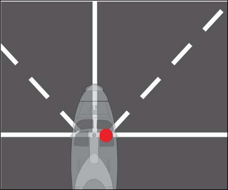
Figure 1 - NVG Line-up Lines
Periphery Lines. Periphery lines shall be marked near the deck edge so that the pilot can avoid the edge or obstructions during landing, and to assist flight deck team situational awareness, particularly at night.
Rotor Clearance Line. A red rotor clearance (safety) line shall be painted on the flight deck to identify the region where the main rotor could sweep, taking into account airborne scatter. The placement of this line shall be conducted considering room for the deck team to stand during manned flight deck launches and recoveries. See Annex A paragraph 4.A.12.
Deck covering. The entire deck area (within the periphery line markings and all aircraft traversing, hangar and parking areas) shall be covered with dark grey non-slip deck covering compound and shall meet the required friction standard (see paras 4.79 and 4.80).
Marking lines. Unless otherwise stated, marking lines shall be 300 mm wide and painted with white non-slip paint. The paint shall also meet the required friction standard (see paras 4.79 and 4.80).
HIFR marking. If the vessel is capable of conducting HIFR operations, a white ‘H’ shall be painted in accordance with Clearance requirements at Annex A and Figure 3 to indicate the appropriate area.
VERTREP markings. If the flight deck is to be used for VERTREP operations, then the VERTREP markings shall be provided in accordance with MPP-02.3.3 Vertical Replenishment (VERTREP) Operating Areas, Marking, Clearances and Lighting.
Hull number. The ship’s hull number, conforming to the standard prescribed in Figure 4, shall also be painted within the periphery line markings to aid in identifying the particular vessel.
Armament Installation/RADHAZ Danger Areas. Armament installation hazard area (e.g. Weapon arc movement line)/RADHAZ danger areas shall not impinge within the periphery line markings of a flight deck area.
Flight Deck Physical Characteristics
Common Deck Markings for Aviation Operations
4.77. Typical Flight Deck Configuration. Figure 2 shows generic flight deck markings for an air capable ship.

Figure 2 - Common Flight Deck Markings
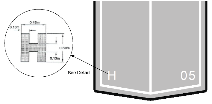
Figure 3 - Typical HIFR Point Markings and Dimensions (Refer to Annex A for ‘H’ location requirements)
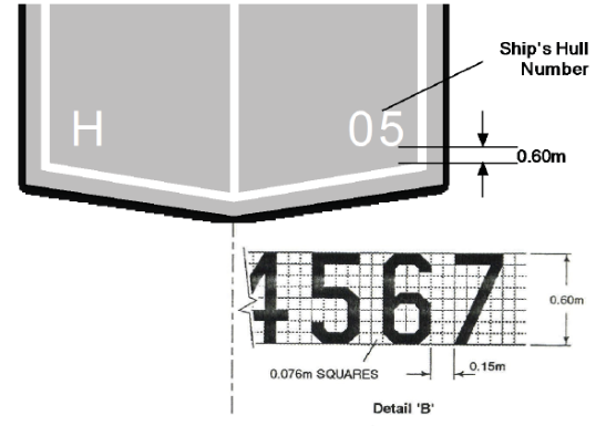
Figure 4 - Typical Marking of Hull Numbers (Detail B is applicable to ships with single spot operating areas e.g. DDG & FFH)
4.78. Deck Strength Criteria. The flight and hangar deck structure shall withstand all loads with aviation operations including landing, parking, traversing and crash loads imposed as a result of the aviation operations for which the vessel is to be certified. This includes elevators, hatches, covers etc when they are part of the aircraft landing, parking, hangar or traversing areas. There shall be no evidence of excessive deformation, deterioration or corrosion, and the welding shall be smooth and even. The design standard to be adopted shall be in accordance with DEF(AUST)5000 Volume 3, Part 1 Hull System Requirements, Surface Ship Structure for all aircraft types for which the ship is to be certified to operate.
Surface Friction Requirements
4.79. Deck friction for new deck coatings shall meet a coefficient of friction of 0.8, and shall comply with the requirements of STANAG 1278.
4.80. Although STANAG 1278 is applicable to measurements on dry flight deck, RAN vessels shall also comply with this requirement for wet flight decks.
4.81. Specifications for paint are detailed at DEF(AUST) 5000 Volume 3, Part 4.
4.82. The flight decks shall be tested for friction factor after initial application of the deck coating
Flight Deck Safety Nets
4.83. Obstructions. Flight deck nets shall be hinged in such a manner that a level or positive angle above the horizontal is achieved with no part of the nets being more than 110 mm above flight deck level when in the lowered position.
4.84. The nets shall be lockable in the lowered positions.
Aircraft Operating Area Access/Egress
4.85. Aircraft operating areas (flight decks, VERTREP and transfer areas) shall have a minimum of two access/egress routes so that in the event of an accident or incident, personnel will be able to escape upwind of the landing area. Access routes shall also facilitate access by CRFF teams.
4.86. Adequacy of the flight deck emergency response and escape arrangements shall be included in any evacuation, escape and rescue analysis.
Helicopter Securing Fittings (Tie-Down Fittings)
4.87. The flight deck area shall provide the means to safely secure aircraft to the deck.
4.88. Strength. The strength of ship tie-down fittings shall be designed so that the structure shall not yield before the lashing breaking load is reached, including the case where up to two lashings are applied simultaneously. Standard lashings are assumed to be TD1A/B lashings, each with a nominal safe working load (SWL) of 10 000 lbf, and minimal proof load of 1.5x SWL in accordance with ANP4412-4314-1, Chapter 7. NAVSEA Drawing 803-1916300 is an acceptable standard.
4.89. Integrity Testing. Tie-down fittings shall be installed and tested in accordance with the design standard used or a qualified Weld Procedure Specification.
4.90. Mounting. The tie-down fittings shall be recessed to comply with the obstruction limitations detailed at Annex A.
4.91. Compatibility. All fittings shall be compatible with the tie-down assembly and lashing in use in the RAN.
4.92. Location. Tie-down fittings shall be installed throughout the aircraft landing area.
4.93. Spacing. Spacing shall be between alternate intersections of a 1.1 m grid. Fittings on other grid patterns or variations due to interferences should be acceptable provided their arrangement allows for maintenance of effective lashing patterns for all aircraft to be operated.
Flight Deck Equipment
4.94. Mooring Aids. Mooring aids (tie-downs) for aircraft securing shall meet the requirements of the aircraft certified for aviation operations and the approved lashing scheme analysis for the ship’s tie-down point pattern (see paragraph 4.92). Indicative numbers of tie-downs required per aircraft shall be found in the aircraft chapters of ANP 3300. Mooring aids quantities shall be included in the ship’s Outfit Allowance List (OAL). Numbers of tie-downs held on-board shall consider operating the flight deck with other aircraft while all organic aircraft are stowed.
4.95. Flammable Liquids. No flammable liquid (gasoline, oil etc) cans, drums or tanks are permitted within 7.6 m of the flight deck periphery line markings.
VERTREP and Transfer Operations
4.96. VERTREP and Transfer Operations in an Air Capable Ship. VERTREP and transfer operations in an air capable ship are normally carried out to the flight deck, and the same facilities are used as for normal flight operations. For the VERTREP facilities, co-located with the Flight deck – requirements for VERTREP in this DASDRM chapter apply.
4.97. Some ships may have a VERTREP and/or transfer area remote from the flight deck. DASA has determined that independent assurance for dedicated VERTREP or Transfer-only facilities do not warrant DASA’s independent assurance. However as many requirements share a number of commonalities and relationship with requirements within the scope of DASA’s assurance. This chapter of DASDRM will maintain benchmark requirements for the design of such facilities, even if they are not subject to the Authority certification.
4.98. For VERTREP or Transfer-only area design requirements regarding markings, clearance and lighting from MPP-02.3.3 Vertical Replenishment (VERTREP) Operating Areas, Marking, Clearances, and Lighting, are to be used as the benchmark.
4.99. Additional to the requirements for markings clearance and lighting. Depending on the scope of intended vertrep operations, other requirements from this chapter (e.g. navigation, communication and control) may also be used as a benchmark for the design.
Landing aids
Lighting and Visual Approach Equipment
4.100. A basic standard of lighting shall support the safe conduct of aviation operations at night (i.e. Level I and II) in all air capable ships.
General Lighting Adjustment and Balance
4.101. Aviation lighting used to orient the pilot and assist in conducting accurate operations about the ship (e.g. deck wash lighting, strip lighting, floodlighting etc.) shall be adjustable (ie have a dimming function) to account for variations in ambient lighting, visibility and pilot preference.
4.102. Each light system shall be individually adjustable for the purpose of achieving a harmonious balance amongst all aviation lights during night and NVD operations.
4.103. Lighting designed for long-distance viewing (3-5 nm) shall be designed such that it is not too bright when viewed in closer proximity, and shall not require manual adjustment to achieve this balance.
4.104. Long Range. The overall lighting configuration of the ship (including obstruction lights, navigation lights and specific aviation lights) shall be designed so that a typical pilot can coarsely ascertain the ship's orientation from approximately 3-5 nm.
4.105. Medium Range. From approximately 0.5 nm, the lighting shall aid the pilot in ascertaining the ship's orientation and enable identification of major features such as the flight deck and forward superstructure, as well as identifying major flight deck markings such as the lateral line-up line and fore/aft position line.
4.106. Close In. While in the flight deck environs, the pilot shall clearly be able to identify the deck edge, lateral line-up line, including vertical lateral line-up line/s and fore/aft position line, as well as seeing hangar features and finer textural detail on the flight deck such as tie-down points. If the pilot is using Night Vision Devices (NVDs), then the NVD lines shall also be clearly visible.
Homing Beacon
4.107. A white homing beacon shall be located as high as practicable on the mast/superstructure. It shall be visible for at least 330 degrees in azimuth and produce approximately 90 flashes per minute. The beacon shall be capable of being dimmed but the flash rate is to remain constant regardless of the light intensity. The minimum visible range on a clear night shall be 6 nm.
Horizon Reference System
4.108. For ships with an aft flight deck, a Horizon Reference System (HRS) shall be installed to provide a representation of the position of the horizon to assist the pilot to recover to the deck at night. The HRS shall be stabilised for roll angles of at least 15°.
4.109. The HRS shall be installed just forward of the flight deck so that it is approximately level with the pilot’s eye line when the aircraft is hovering over the deck.
Glide Slope Indicator
4.110. A gyroscopically stabilised glide slope indicator (SGSI) shall be installed on the extended axis of the preferred approach. The SGSI shall conform to the requirements of STANAG 1236. The SGSI shall be a Type NVD-YGR (detailed in STANAG 1236(4)). The centre of the green band (glide slop) shall be 3° above the horizontal with the projection pattern illustrated at Figure 5.
4.111. When more than one night approach path to the flight deck is required, the SGSI shall be trainable to align with all approach paths.
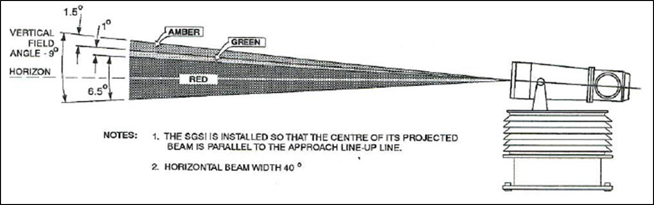
Figure 5 - Stabilised Glide Slope Indicator
Obstruction Lights
4.112. A minimum of two blue lights shall be installed to mark both the top and outboard limits of shipboard structures closest to the operating area. The lights shall be controlled by a single ON/OFF switch. Dimming shall not extinguish the lights.
Level III Operations – All Ships
4.113. For Level III (three) daylight operations, a deck status light system and emergency wave-off light system shall be installed. Where the aircraft is expected to be maintained overnight, maintenance floodlighting (fixed or portable), shall be available.
Deck Status Light System
4.114. The deck status lighting system shall convey the status of the flight deck through a combination of lights, symbols and/or flashing in accordance with one of the systems detailed in STANAG 1472; however, the system described in Annex B of STANAG 1472 is preferred by the RAN (Steady Three Colour Light With Symbology Status Display)
4.115. The status indication shall be clearly visible in direct sunlight, but also dimmable for night and NVD operations, however the dimming shall not extinguish the lights.
4.116. The NVD compatibility and intensities detailed in STANAG 1472 shall be complied with.
4.117. Controls shall be provided at the HCO/LSO/FDO to enable the operator to select the deck status system to red, amber or green. Selection of red, amber or green shall be mutually exclusive.
4.118. A deck status repeater shall be included on the Bridge and AC display/control consoles. This repeater represents the deck status as selected by the HCO/LSO/FDO.
Emergency Wave-Off Light System
4.119. A wave-off function shall be implemented to provide an indication to the pilot to abort the approach. The wave-off indication shall be clearly visible in direct sunlight, but also dimmable for night operations, however the dimming shall not extinguish the lights. Ranges shall be applicable for the hazards that wave-off shall be initiated to control (for example greatest RADHAZ range).
4.120. For commonality with existing RAN systems, the wave-off lighting should be implemented by two red wave-off lights located adjacent to and on either side of the SGSI, in conjunction with flashing of the red deck status light.
4.121. Alternatively, wave-off functionality could be achieved by alternative lighting systems (such as a flashing Pilot Information Display (PID) and/or flashing red deck wash / strip lights) provided that the indication is unambiguous and visible by day and night. Flashing rates required for NVD compatibility shall not coincide with flashing rates of either the SGSI or PID.
Ship Motion Parameters
4.122. Ship motion displays for aviation operations shall display ship’s pitch and roll attitude as a minimum.
4.123. Dynamic pitch and roll should also be displayed by subtracting trim from absolute pitch and subtracting list/heel from absolute roll. Trim is calculated by averaging pitch over a configurable time period. Similarly, list/heel is calculated by averaging roll over a configurable time period.
4.124. Ship Motion Measurement. Pitch and roll indicators shall be accurate to ±0.25°, with a display resolution of 0.1°, and angular range of ±45°.
4.125. Ship Motion Limits Monitoring. Ship motion displays shall include a capability to set desired pitch and roll limits. When the pitch and roll limits are exceeded, the display shall provide a visual indication to the operator that the limits have been exceeded and what the maximum pitch and roll was. If dynamic motion limits are employed, then it shall be possible to set dynamic limits and display exceedance of the limits.
4.126. The ship motion display shall display historical motion and limit exceedance for a configurable time period between one minute and 10 minutes. The system may provide the ability to record ship motion for 24 hours.
Wind Speed and Direction System Displays
4.127. Relative wind displays shall display the average wind speed and direction over a 10- second moving average.
4.128. Relative wind displays should display the instantaneous relative wind speed and direction based on a one-second average. Such a display shall also include a history of the previous 10 seconds of instantaneous wind.
4.129. The display of relative wind shall include a numeric display of the 10-second moving average as well as a relative wind plot showing the average and instantaneous relative wind.
4.130. The relative wind display should provide the time-averaging period.
4.131. The relative wind display shall provide a clear indication of which anemometer (or algorithm) is used as the data source.
4.132. The relative wind display should overlay the wind speed and direction display with the approved relative wind envelope to improve the ease of determining whether the relative wind is within limits prescribed in the SHOL. This can assist operators in determining ships course and speeds that will place relative winds within SHOL.
Anemometers
4.133. Anemometer Accuracy. Anemometer sensors used in the Wind Speed and Direction System (WSDS) shall have a speed accuracy better than 3% and a directional accuracy of ±5°. The operating range shall be as per DEFAUST(5000) Vol 10, Part 2, paragraph 5.4.4.1, i.e. from 0.5 to 60 m/s.
Anemometer Placement
4.134. Anemometers shall be positioned in clear air above the ship’s superstructure and outside the influence of the ship’s air-wake.
4.135. If the location does not provide an unobstructed airflow throughout all azimuths (i.e. 360°), then two or more anemometers shall be mounted. Larger ships may require additional anemometers further aft to detect winds abaft the beam.
4.136. Anemometers sited on masts shall be in free air, in a location uncluttered by adjacent equipment with at least 3.0m radius free air space around each anemometer.
4.137. Anemometers shall be positioned so that they are not subject to electromagnetic interference from ship’s emitters.
Course and Speed
4.138. Ship’s course and speed displays shall be available at specified stations as per Table 4 (located at para 4.154). The operator should be able to select between either speed through the water (log speed) and heading from the ship’s gyro, or GPS speed and track.
4.139. The course, speed and position navigational accuracy requirements shall be in accordance with DEF(AUST) 5000 Volume 10 Part 2.
QNH
4.140. A reading of QNH (atmospheric pressure—Q at Nautical Height) in Hectopascals shall be available at specified stations as per Table 4. QNH may be sourced from a calibrated ship-based barometer as per DEF(AUST)5000 Volume 10 Part 2 (which, in turn, refers to WMO Publication 08), or from an airfield weather station report that is valid for the time and location of the ship.
Outside Air Temperature
4.141. A reading of Outside Air Temperature (OAT) in degrees Celsius shall be available from the ship-based weather station as per DEF(AUST)5000 Volume 10 Part 2 (which, in turn, refers to WMO Publication 08).
Signalling Aids
4.142. Signalling aids shall be stowed adjacent to the FDO/FDM position:
Day Signalling. The FDO/FDM shall use hands or marshalling bats to conduct day signalling.
Night Signalling. The FDO/FDM shall use two battery-powered wands to conduct night signalling with a spare wand available. The wands shall be NVG friendly in accordance with DEFSTAN 02-587, and all three wands shall be the same colour.
Navigation and Tracking Aids for Level I and Level II Certification
4.143. In general terms, the aids for Level I aviation operations shall satisfy the following three requirements:
Assist aircraft navigating to the ship from a long range.
Allow aircraft to make an instrument approach to the ship.
Allow the ship’s command team to maintain situational awareness of air assets in the vicinity of the ship.
4.144. The required navigation and tracking equipment function and performance characteristics as detailed in Table 2 shall be provided to support Level I or Level II aviation operations as part of a Shipborne Heliport Certification. A ship system may comprise of combined sensors/systems to provide the detection and recovery requirements as specified. Systems shall be proven to work in envisaged operating conditions (including varying levels of precipitation and sea state) based on the vessels envisaged scope of operations.
4.145. For Level I certification, flight testing shall be conducted with representative aircraft types and number of aircraft to confirm that the system can achieve the requisite performance and functionality.
Table 2 - Navigation Equipment for Level I and II Operations
|
|
Navigation |
Separation |
Instrument Approach |
|
Level I |
Mandatory Ship radar system to detect aircraft from at least 20 nm and 1000 ft and 10 nm at 400 ft from all azimuths. Maintain consistent contact with aircraft as aircraft nears the instrument approach gate (2 nm, 400 ft).
Plus, at least one of the following:
It is desirable to have these items fitted |
Mandatory Ship radar system must be able to maintain track of helicopters within the SCZ. Typically 0.5-2 nm at 200-400 ft, and 0.25-0.5 nm 100-200 ft System must have the ability to maintain multiple tracks in the SCZ (the number to be defined by the envisaged scope of operations) System should be able to display individual contacts as designated by the operator.
Desirable
|
Mandatory Radar tracking to be maintained from the gate (2 nm, 400 ft), top of decent (1.2 nm, 400 ft), through decent to the missed approach point (0.2 nm, 125 ft). Coverage to ±20° of approach path, as well as steep or shallow approaches. Maintain tracking through missed approach (possible less than 125 ft) to 400 ft. Maintain tracking during ELVA approach. Plus, at least one of the following:
|
|
Level II |
Mandatory
OR
OR
Desirable
|
Desirable
|
Desirable (night visual approach may be conducted)
|
4.146. Identification Friend or Foe (IFF). A ship certified to Level I aviation operations shall have an identification friend or foe (IFF) interrogator capable of interrogating in Modes 1, 2, 3, C 4 and 5 (Level II) certified to either US AIMS 1000B Standards suite or NATO STANAG 4193. The helicopter control display shall be capable of displaying all modes and emergency IFF codes. Trials and periodic tests of the equipment shall be conducted in accordance with ANP 3412-4202.
Recovery Assist, and Securing System
4.147. Where an operational requirement exists, a system shall be provided that assists in the recovery of the aircraft and/or secures the aircraft to the flight deck upon recovery or prior to launch.
4.148. Wire recovery systems shall comply with requirements of MPP 02(H) Annex A013. Harpoon systems shall comply with the requirements of MPP02(H) Annex A014 and STANAG 1276.
Aviation Services
HIFR Heading Lights
4.149. For ships requiring Level I (one) and II (two), Class 6 (HIFR) certification, three heading lights shall be installed in accordance with Figure 6. The HIFR heading lights shall be controlled by a single dimmer control and on/off switch. The maximum distance between the HIFR ‘H’ and the aft-most HIFR heading light shall be 75 m (‘E’, as specified on Figure 6).
4.150. HIFR heading lights shall be installed as far to port as feasible. All three lights shall be the same distance from the ship’s centreline and shall be simultaneously visible to the pilot during the refuelling phase of the HIFR operation. The pilot is positioned opposite the hose pick-up spot at approximately 9 m to the port side of the ship at a height of 18 m. All three HIFR heading lights shall be the same distance above the ship’s base line. All HIFR heading lights shall be installed between 6 m to 7 m above the HIFR deck.
4.151. If HIFR heading light(s) extend into the firing sector of the ship’s guns and/or missiles, the light(s) shall be installed on a portable support.
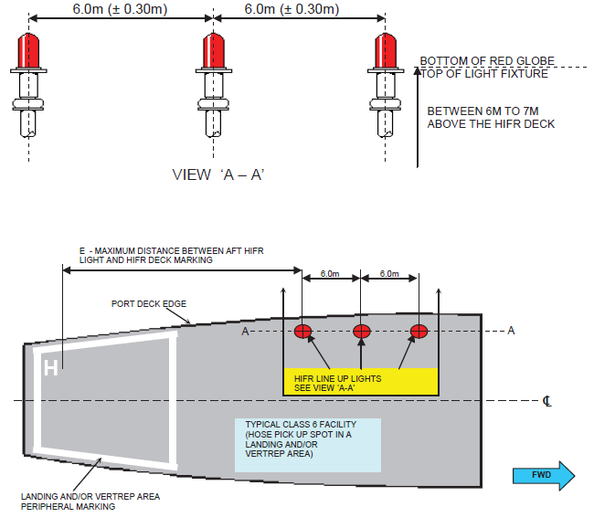
Figure 6 - Typical Arrangement of Visual Aids for HIFR Areas
HIFR
4.152. Fuelling System Requirements for HIFR. The helicopter in-flight refuelling (HIFR) fuel system shall provide a minimum flow rate of 230 l/min at a height of 65 ft above sea level, providing 50 psi at the refuelling nozzle. A lesser flow rate and pressure, as per STANAG 3847, may be acceptable provided that the system can refuel an aircraft in a timeframe that is operationally acceptable.
Aviation Station Configuration
4.153. Aviation stations shall be provided to support the ship’s staff involved in control of the aviation evolution as defined in ANP 3300 (principally HCO, AC, LSO, FDO, FDM, and HD). Table 3 shall be used to determine the aviation station configuration that is appropriate to the intended Level and Class of operation.
Table 3 - Aviation Station Configurations
|
|
Level I |
Level II |
Level III |
|||||||||
|
|
Class |
Class |
Class |
|||||||||
|
Aviation Station Configuration |
1,2,3 |
4,5 |
6 |
7 |
1,2,3 |
4,5 |
6 |
7 |
1,2,3 |
4,5 |
6 |
7 |
|
Bridge, AC, HCO, LSO (RAST Operations) |
X |
X |
X |
X |
X |
X |
X |
X |
X |
X |
X |
X |
|
Bridge, AC, HCO (No RAST, but maybe ASIST) |
X |
X |
X |
X |
X |
X |
X |
X |
X |
X |
X |
X |
|
Bridge, HCO |
|
|
|
|
X |
X |
X |
X |
X |
X |
X |
X |
|
Bridge, FDO |
|
|
|
|
p |
p |
p |
p |
X |
X |
X |
X |
|
VERTREP Only Control Station |
|
|
|
|
|
f |
|
|
|
X |
|
|
|
Transfer Only Control Station |
|
|
|
|
|
|
|
X |
|
|
|
X |
Notes
p – it is possible to conduct Level II operations with just a Bridge and FDO, but this is not recommended
f – night VERTREP is presently only conducted in specific circumstances by RAN
Aviation Station Equipment
4.154. Table 4 stipulates the minimum required equipment at each of the aviation stations for helicopter operations.
Table 4 - Aviation Station Equipment
|
Equipment |
Helicopter Control Station (HCO/LSO/FDO) |
Bridge |
Aircraft Controller Station |
VERTREP/Transfer Control Station |
|
Ship Motion Display |
Required |
Required |
Required |
Required |
|
Relative wind speed and direction |
Required |
Required |
Required |
Required |
|
Course and speed displays |
Required |
Required |
Required |
Desirable |
|
QNH and OAT available |
Required |
|
Required |
|
|
Lighting controls for flight deck and the associated aviation lights, such as the homing beacon and HIFR line-up lights (including lighting intensity controls) |
Required |
|
|
|
|
Controls for deck-status display |
Required |
|
|
|
|
Deck-status display status so that the OOW/OPSO maintains situational awareness of aspects that may impact on the safety of the ship. |
|
Required |
Required |
|
|
Controls (and display) for the emergency wave-off. |
Required |
Required |
Required |
|
|
If the ship does not have a dedicated emergency wave off switch, then the equivalent functionality shall be provided by having override control of Deck Status indication to change from ‘approved’ to ‘not-approved’. |
|
Required |
Required |
|
|
Fuel emergency stop |
Required |
|
|
|
|
Crash-on-deck alarm control |
Required |
Required |
Desirable |
Desirable |
|
A means of displaying SHOL |
Required |
Required |
Required |
Desirable |
|
A means of determining ship course and speeds that will place relative wind within SHOL. |
Desirable |
Required |
Required |
|
|
CCTV Displays |
See 4.28 |
See 4.28 |
See 4.28 |
See 4.28 |
|
CCTV Camera Control |
Required |
|
|
|
|
CCTV Recorder Control |
Required |
|
|
|
|
Command Request and Approval System |
Required |
Required |
Required |
|
|
Communications equipment |
Required |
Required |
Required |
Required |
Control Station Field of View
4.155. Helicopter Control Station (HCS) Field of View. The HCS shall be located so that the operator can view both the aircraft and the aircraft operating area without moving away from the controls. The view from the position shall be unobstructed and include all flight deck areas normally occupied by personnel during flight operations and all of the aircraft during approach, hover, landing and take-off.
4.156. Landing Safety Officer Station Field of View. In addition to accommodating RAST/ASIST controls, the Landing Safety Officer (LSO) control station shall be located so that the RSD/helicopter main probe interface, hook-up team and traversing crew can be viewed from the LSO station. The use of a CCTV camera system to display live video of the RSD/helicopter main probe interface may be permitted.
4.157. VERTREP Control Station Location and Field of View. A VERTREP Control Station (VCS) shall be provided outside the periphery line markings of the VERTREP area, but from where the Helicopter Director (HD) shall have a clear view of the VERTREP area and the aircraft involved in the operation. The VCS shall be located such that it has ready access to the VERTREP area.
General Display Requirements
4.158. Displays shall be collocated as far as practicable, with the layout based upon a compromise of importance (safety), frequency of use, and logical grouping.
4.159. Display panels shall be visible from the operator’s normal operating position and orientation.
4.160. All displays shall have a wide adjustment of brightness in order to be readable from bright sunlight conditions down to very dark conditions.
4.161. If used at night, displays or control lighting in the Bridge, Landing Safety Officer (LSO) Station, FDO/FDM Station and Helicopter Control Station (HCS) shall comply with NVD Compatibility requirements for Category ‘C’ lights as defined in DEFSTAN 02-587.
4.162. Human factors design shall comply with DEF(AUST)5000 Vol 06 Pt 02 Sec 03.
General Control Requirements
4.163. All controls, indicator lamps, switches and switch positions shall be identified by appropriate nameplates or engraving, or graphical user interface (GUI) equivalent.
4.164. Dimmer/brightness controls for lights shall be designed to operate in a logical manner (e.g. to increase intensity rotate control knobs clockwise or slide upwards for a sliding control).
4.165. Switches and controls shall be operable with or without gloves (anti-flash).
General Requirements for Stations on Weather Decks
4.166. If the station (FDO/FDM, VERTREP, Transfer) is located on a weather deck, then:
The control panels shall be watertight.
Any displays shall be sunlight-readable.
Any controls or equipment shall be secured so as not to create a Foreign Object Damage (FOD) hazard.
General Compartment Requirements for Aviation Stations
4.167. Area lighting in the HCS, LSO Station and Bridge (where the pilot may see the Bridge during approach) shall comply with NVD Compatibility requirements for Category ‘C’ lights as defined in DEFSTAN 02-587. This ensures that lights emanating from windows shall not degrade NVD images for aircrew, but also facilitate the use of NVDs by the HCO or deck staff, if desired.
4.168. Windows shall incorporate windscreen wipers, demisting and tinting consistent with the requirements of the Bridge windows detailed in DEF(AUST)5000 Volume 10, Part 2, paragraph 5.6.4.
Lighting Controls
4.169. The Helicopter Control Station shall include controls for all aviation lights and visual aids (such as SGSI), including intensity controls.
Aircraft Controller (AC) Station
4.170. A dedicated AC control position shall incorporate a suitable helicopter control radar display. The display shall be integrated to the ship’s Combat Management System located in the Operations Room. As a minimum, information shall include ship course and speed, ship position, helicopter identification, helicopter position and helicopter range and bearing to own ship. If available height shall also be displayed.
4.171. The display shall be equipped with suitable overlays or have an operator input facility for projection of standard helicopter approach patterns.
Explosive ordnance and flammables
4.172. Forward Firing and High Explosive Weapon Loading. Risks analysis associated with operating of forward firing and high explosive ordnance shall be conducted in accordance with eDEOP101 Reg 5.4 to define design requirements.
4.173. Magazines and Ready Use Magazines. Magazines and ready-use magazines of locker size shall not be located on exposed decks within the helicopter clearance envelope/s (Annex A). Ship’s Helicopter Operating Instructions shall specify that all weather-deck ammunition magazines and ready-use lockers in the vicinity of the aircraft operating area shall be closed during helicopter operations. Requirements of DEF(AUST) 5000 Vol 6 Pt 05 Sect 03 shall be adhered to for magazine and ready use magazine design.
RADHAZ
4.174. RADHAZ. Emitter systems (RADAR, Communication, Laser systems) that may be hazardous to aircrew and aircraft shall comply with DEF(AUST) 5000 Volume 2 Part 11, ANP4411-1314 and AECP-2(C). Software RADHAZ controls shall also meet the requirements of DEF(AUST) 5000 Vol 2 Pt 14.
Aviation incident response
Safety and Rescue Facilities
4.175. Flight Deck Crash Rescue Equipment. Equipment shall be readily available at the flight deck of all air capable ships for the conduct of emergency rescue operations in support of aircraft which have crashed. Equipment scales are laid down NAP 7002.002-2M and ANP 4316.
Ditched Aircrew Rescue
4.176. Crash Rescue Boat. A ship’s boat of inflatable, rigid inflatable or rigid hull design shall be designated as the crash rescue boat in all air capable ships.
4.177. All available ship’s boats may be required for aircrew rescue. For the required speed of reaction, the designated crash rescue boat shall be immediately available and equipped for personnel rescue.
4.178. The crash rescue boat's minimum equipment requirements are listed in ANP 3300.
4.179. The crash rescue boat shall be able to operate to the maximum sea state in which all required aircraft can conduct operations to the ship.
Crash Alarm
4.180. An aircraft crash alarm shall be installed with an actuating switch at the HCS, LSO Station, FDO Station and Bridge. A crash alarm switch shall also be installed at VERTREP or transfer Control Stations when the Bridge does not have a clear view of the VERTREP or transfer area. The switch shall be a stand-alone item and shall be clearly identified ’CRASH ALARM’. The alarm shall sound at all broadcast and alarms system speaker locations.
Control Stations and Windows Overlooking the Flight Deck
4.181. Control Station Bulkheads and Windows overlooking the flight deck shall be ballistic-resistant for the purpose of protecting occupants in the event of a helicopter crash. The ballistic protection characteristics shall comply with DEF(AUST) 5000, Volume 7, Part 23, Section 5, with aviation control stations for all ship types being classified as ‘High Value Compartments’ on Platform Type A ships to ensure fragment mitigation is included.
4.182. For windows mounted within the Flight Deck area (e.g. RAST Control Station) the window and frame structure shall be as a minimum, equally as strong in all respects as its deck surrounding structure.