4.A.1. Clearance Criteria for Landing and Launching Operations. For a ship to be cleared and certified to land and launch a helicopter, certain minimum clearances within defined clearance areas and approach flight paths are required and shall be assessed separately for each helicopter type under consideration. The clearances given in this section are the minimums allowed for safe operations. Newly-designed flight-decks should aim for greater clearances than the minimum to promote safer and more capable aviation operations at sea.
4.A.2. Scatter. The obstruction clearance criteria described in this section is based upon the concept that during helicopter operations to ships, the helicopter position will vary each time from what may be considered an ideal approach/departure profile and landing position. The scatter may be classified into an airborne phase and a landing phase. The airborne phase applies during the approach to and departure from a point above the touchdown position. The landing phase applies to aircraft touching down on the flight deck.
4.A.3. Airborne Scatter. This is an allowance for deviation of the helicopter from the optimum flight path whilst positioning for landing or departing after take-off. The airborne scatter distance is determined by the rotor diameter of the helicopter. The scatter is applied along the fore-and-aft axis of the flight deck centreline; however, the associated clearance volume is considered to extend laterally to represent the aircraft transitioning left or right for departure (or for landings applicable to lateral approaches). The airborne scatter is defined in Table A-1 Airborne Scatter below.
Table A-1 - Airborne Scatter
|
Rotor Diameter |
Airborne Scatter |
|
|
Single Spot |
Multi Spot |
|
|
Up to 12.0 m (39 ft) |
3.0m (10 ft) |
2.4m (8 ft) |
|
12.01 to 15.0 m (49 ft) |
3.5m (12 ft) |
2.7m (9 ft) |
|
Over 15.01 m (49 ft) |
4.5m (15 ft) |
3.0m (10 ft) |
4.A.4. Landing Scatter. This is an allowance for deviation of the helicopter from the optimum flight path immediately prior to touchdown and immediately post lift-off. The landing scatter distance is determined by the maximum AUW of the helicopter. It is applied along the fore/aft and lateral axes of the flight deck centreline. Table A-2 Landing Scatter defines the landing scatter.
Table A-2 - Landing Scatter
|
Maximum AUW |
Landing Scatter |
|
|
Single Spot |
Multi Spot |
|
|
Up to 5400 kg (12 000 lb) |
2.4 m (8 ft) |
1.8m (6 ft) |
|
5400 kg (12 000 lb) and Above |
3.0 m (10 ft) |
2.4 m (8 ft) |
4.A.5. Heading Error. Heading error is an allowance for deviation of the helicopter from the intended landing heading. It is superimposed on landing scatter to calculate all possible wheel landing positions. For all helicopters, the heading error is ±20°. Heading error shall be calculated using the main rotor centre as the point of rotation (or designed Yaw pivot point if different).
4.A.6. Areas and Volumes. The system for determining obstruction clearances involves four different areas. Each area has allowable obstruction heights. The approach to conceptualising the areas is to define a clearance volume that commences at a prescribed height above the flight deck and extend upwards. By applying such a volume to an existing 3D model of a ship, the compliance finder shall establish if there is an overlap between an obstruction and the clearance volume (ideally, there should not be any incursions into the clearance volume). The ‘datum’ for the construction of the volumes is the ‘reference position’.
4.A.7. Reference Position. The reference position is the intersection of the fore/aft position line (also known as the Pilots Eye Line—PEL, or bum line) and the lateral line-up line painted on the flight deck. The pilot’s eye line shall pass through the fore/aft position line, and the aircraft shall be centred on the lateral line-up line.
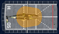
4.A.8. Touchdown Clearance Area (TCA). The Touchdown Clearance Area is that area of the flight deck within which the landing gear of a helicopter shall alight. It is centred on the optimum landing position, includes allowance for landing scatter and heading error, and ensures clearance from obstacles for the landing gear. Where essential and to the benefit of flight operations, obstructions to a maximum of 25 mm in height are permitted provided that they are contoured or faired and are shaped in such a fashion that they do not provide a hazard to aircraft wheels or to personnel. A top view of an MRH90 TCA on a generic flight deck is shown at Figure A-1 (A). (The base of the volume is 25 mm above the flight deck).
NOTE: The deck edge is also considered to be an obstruction.
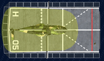
4.A.9. Fuselage Clearance Area (FCA). The Fuselage Clearance Area is that area of the flight deck outside the TCA for which adequate obstruction clearance is provided for the main rotor, fuselage and the most rear part of the fuselage (or tail rotor) likely to strike the deck. It is centred on the optimum landing position and includes allowance for landing scatter and heading error. Where essential and to the benefit of flight operations, individual deck hardware smoothly contoured to a required minimum slope of 1 in 3 and not exceeding 0.11 m in height are permitted. Slope material shall be capable of withstanding aircraft landing forces. Where fitted, deck wash lights shall be installed on or outside the periphery line markings as close as possible to the deck edge and the adjusted height shall not exceed 0.30 m. A top view of an MRH90 FCA on a generic flight deck is shown at Figure A-1 (The base of the volume is 0.11 m above the flight deck).
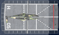
4.A.10. Fuselage and Tail Rotor Swept Area (FTRSA). This is the area outside the FCA swept by the fuselage and tail rotor whilst positioning for landing or departing after take-off, having allowed for airborne scatter in the fore/aft axis. The FTRSA extends laterally infinitely on any side that the helicopter may launch or recover from. If the helicopter is constrained in a particular direction, then the clearance area shall extend a distance to account only for airborne scatter. For stern approaches, the FTRSA is also swept from the reference position infinitely aft, with airborne scatter in the lateral axis. Obstructions shall not exceed 0.61 m in height. A top view of an MRH90 FTRSA on a generic flight deck is shown at Figure A-1 (The base of the volume is 0.61 m above the flight deck).
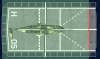
4.A.11. Main Rotor Swept Area (MRSA). This is the area outside the FTRSA potentially swept by the main rotor whilst positioning for landing or departing after take-off, having allowed for airborne scatter. The MRSA extends laterally infinitely on any side that the helicopter may launch or recover from. If the helicopter is constrained in a particular direction, then the clearance area shall extend a distance to account only for airborne scatter. For stern approaches, the MRSA is also swept from the reference position infinitely aft, with airborne scatter in the lateral axis. Obstructions shall not exceed one eighth of the main rotor diameter or 1.5 m, whichever is the lesser. A top view of an MRH90 MRSA on a generic flight deck is shown at Figure A-1 (The base of the volume is 1.5 m above the flight deck).
4.A.12. The optimal location of the reference position shall be determined by balancing the clearance between the MRSA and forward obstructions, with the requirement to access the tail rotor with the helicopter landed in the extreme aft position. Other considerations, such as detailed in 4.A.12 and 4.A.13 may bias the reference position to be further aft as well as considerations for enabling room for the deck team to stand during manned flight deck launches and recoveries. However, operational and maintenance considerations (such as troop movements, traversing equipment, lashing patterns etc) may bias the reference position to be further forward. Finally, the size of the flight deck may preclude access to the tail rotor for maintenance, with the requirement depending on the operational intent of the ship (for example, if the helicopter is intended only for launch and recovery operations on the vessel and not permanent embarkation tail maintenance may not be required). In this case, the design of the reference position shall ensure that the TCA is contained within the flight deck, and that the TCA and FCA clearances are complied with.
4.A.13. With the aircraft in the reference position, the pilots’ field of view shall not be restricted by the ship superstructure by more than ±30°.
4.A.14. There shall be sufficient clearance between the main rotor and the aft superstructure to avoid recirculation effects between the main rotor and the superstructure.
4.A.15. Considerations for deck width and the periphery line markings shall ensure the FCA is contained within the flight deck (including where pylons/wings are fitted to the helicopter). Deck width shall enable manual blade fold requirements for primary aircraft with manual blade fold.
|
|
|
|
Figure A-1 - Component Landing and Swept Areas Figure
A) Touchdown Clearance Area (TCA)
B) Fuselage Clearance Area (FCA)
C) Fuselage and Tail Rotor Swept Area (FTRSA)
D) Main Rotor Swept Area (MRSA)
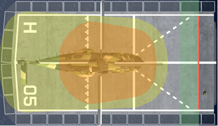
Figure A-2 - Combined Landing and Swept Areas

Figure A-3 - Combined Landing and Swept Areas – Side View
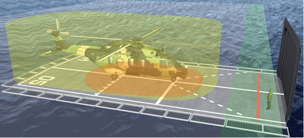
Figure A-4 - Combined Landing and Swept Areas – 3D View
4.A.16. VERTREP Obstruction Clearance Criteria. VERTREP obstruction clearances shall be based upon the four obstruction clearance volumes as detailed in Table A-3 Application of Clearance Volumes to VERTREP Clearances where the height of the aircraft is offset vertically from the deck by 0.61 m for Class 4 VERTREP and by 3.71 m for Class 5 VERTREP.
|
Type of VERTREP |
Application Clearance Volumes |
|
Type 1 |
Apply TCA and FCA whilst centred over the VERTREP area, apply landing scatter and ±20° heading error, with the aircraft aligned athwartships. Apply FTRSA and MRSA with airborne scatter with the aircraft aligned athwartships, running athwartships along the VERTREP line. Offset the FTRSA and MRSA clearance volumes upward by 0.61m for Class 4 VERTREP and by 3.71 m for Class 5 VERTREP. (This allows for 0.89 m of vertical scatter during VERTREP). |
|
Type 2 |
Apply TCA and FCA whilst centred over the VERTREP area, apply landing scatter and heading error from ahead ± 90°. Apply FTRSA and MRSA with airborne scatter and heading error from ahead ± 90° with the aircraft aligned forward, along the VERTREP line (running athwartships) Offset the FTRSA and MRSA clearance volumes upward by 0.61m for Class 4 VERTREP and by 3.71 m for Class 5 VERTREP. (This allows for 0.89 m of vertical scatter during VERTREP). |
|
Type 2A |
As per Type 2, using alternative Tee-Ball-lines as reference. |
|
Type 3 |
Apply TCA and FCA whilst centred over the VERTREP area, apply landing scatter and heading error equating to retaining gearboxes within T-lines (aircraft nominally aligned athwartships). Apply FTRSA and MRSA, apply landing scatter and heading error equating to retaining gearboxes within T-line, running athwartships along the VERTREP line. Offset the FTRSA and MRSA clearance volumes upward by 0.61m for Class 4 VERTREP and by 3.71 m for Class 5 VERTREP. (This allows for 0.89 m of vertical scatter during VERTREP). |
4.A.17. Transfer Obstruction Clearance Criteria. The minimum hover height for Transfer shall be determined based on a hover position that maintains the aircraft clearance volumes (TCA, FCA, FTRSA, MRSA) free from obstructions offset by winch height and a component for vertical scatter.
4.A.18. Clearance Requirements for a Midships Landing Area. The obstruction clearance criteria detailed in paragraphs 4.A.2 through to 4.A.5, and 4.A.6 through to 4.A.11 shall be applied to midships landing areas.
4.A.19. Clearance Criteria for Dual Main Rotor Helicopters operating to a Midships Landing Area. Similarly, the obstruction clearance criteria detailed in 4.A.2 through to 4.A.5, and 4.A.6 through to 4.A.11 shall be applied to dual main rotor helicopters operating to a midships landing area, although the tail rotor dimensions shall be replaced by the rear main rotor and aft fuselage.
4.A.20. Clearance Criteria for a Forward Landing Area. The clearance requirements for a midships landing area shall be applied.
4.A.21. When a deck area is used exclusively for HIFR operations, the minimum area size, as defined by the outside dimensions of the periphery line markings, shall be 3.3 m2. The HIFR area shall be approximately square in shape. Within the periphery line markings, a block letter ‘H’ (as detailed in Figure 3 of parent document, or pictorially at Figure A-2 Combined Landing and Swept Areas shall be painted to designate the spot over which the helicopter shall lower its hoist in order to pick up the refuelling hose.
4.A.22. When located in a landing and/or VERTREP area, the HIFR pick-up spot shall be located on the port side.
4.A.23. The minimum hover height for HIFR shall be determined based on a hover position that maintains the aircraft clearance volumes (TCA, FCA, FTRSA, MRSA) free from obstructions. The minimum hover height shall be increased by 0.89 m to account for vertical scatter.
4.A.24. In addition, the area between the fuelling station and the pick-up point shall be clear of obstructions. Deck equipment and hardware shall not snag or damage the HIFR hose.