MODE
PART 1
PART 2
PART 3
PART 4
PART 5
Air Land (AL)

N/A
N/A
Air Drop (AD)
N/A
External Lift (EL)
Item 1.4.3 (for item restraint)
N/A
N/A
This Annex contains instruction and guidance for application of the Aerial Delivery Standard cited at Section 5, Chapter 5, Paragraphs 5.5 and 5.6. This Annex consists of the following parts:
Part 1 – Applicable to load items to be internally transported by Defence fixed and/or rotary wing cargo aircraft, termed Air Land (AL) transport.
Part 2 – Applicable to load items to be air dropped by Defence fixed wing cargo aircraft, termed Air Drop (AD) transport.
Part 3 – Applicable to load items to be suspended beneath Defence rotary wing aircraft for the purposes of transporting items, termed External Lift (EL) transport (also commonly known as Helicopter Sling Loading (HSL)).
Part 4 – Applicable to attachment points, lifting provisions and cargo tie down provisions and is therefore applicable to load items to be transported via AL, AD and EL modes.
Part 5 – Applicable to attachment points used for AD and AL modes of transport.
|
MODE |
PART 1 |
PART 2 |
PART 3 |
PART 4 |
PART 5 |
|
Air Land (AL) |
|
N/A |
N/A |
|
|
|
Air Drop (AD) |
|
|
N/A |
|
|
|
External Lift (EL) |
Item 1.4.3 (for item restraint) |
N/A |
|
|
N/A |
Definitions for the verification methods are contained at Annex B of Section 5, Chapter 5. Unless otherwise specified, only one of the listed verification methods for each design requirement needs to be applied.
Table 1 presents instructions and guidance for application of the Aerial Delivery standard for AL transport via fixed and rotary wing aircraft. Table 1 makes reference to United States and international standards (as cited by Section 5, Chapter 5, Paragraph 5.5) to establish the requirement with some Australian supplements (as cited by Section 5, Chapter 5, Paragraph 5.6). The Australian Air Publications are used for design data. Where the international standards refer to Air Transportability Test Loading Activity (USAF), AMTDU is the applicable agency.
The following standards and publications contain the relevant requirements and design data, and are to be read in conjunction with this part:
Adopted Standards (as cited by Section 5, Chapter 5, Paragraph 5)
MIL-STD-1791D Change 1 – Designing for Internal Aerial Delivery in Fixed Wing Aircraft
MIL-DTL-27443F Pallets, Cargo, Aircraft, Type HCU-6/E, HCU-12/E
IATA Dangerous Goods Regulations (58th Edition)
ISO Standards for Freight Containers (ISO668, ISO1161, ISO1496 Series, ISO3874)
Relevant Guidance Documents
MIL-STD-810G Environmental Engineering Considerations and Laboratory Tests
Design Data
AAP7211.031-9 Loading Instructions Hercules C-130J-30 (Section 4)
TO 1C-17A-9 Loading Instructions C-17A Aircraft (Section 4) or aircraft data from Appendix B.4 of MIL-STD-1791D Change 1
AAP7210.026-1 Flight Manual Chinook CH-47F (Chapter 6)
AAP7211.045-9 C-27J Spartan Aircraft Cargo Loading and Offloading Manual (Section 4)
AAP7210.023-1B Flight Manual MRH90 Taipan (Section 1)
AAP7210.015-1 Flight Manual Black Hawk (S-70A-9) (Section 8)
Air Force Air Movements Manual.
Table 1 – Air Land Transport Certification Requirements and Verification
|
Item |
Instruction for Application of Standard |
Guidance |
Verification |
||||||||||||||
|
Load Item Size |
|||||||||||||||||
|
1.1.1 |
Cargo Compartment Clearances Refer to MIL-STD-1791D Ch1, Section 5, Clause 5.3.1.1 noting the following Australian aircraft design data applies:
|
Load items meeting these requirements facilitates compatibility with the applicable ADF aircraft. The design of load items should be such that they can be loaded aboard ADF aircraft in their air transport configuration (which may include secondary cargo, see guidance under Item 1.4.2) whenever possible. The design goal is to qualify items for Air Land transport under the most restrictive combination of requirements. When necessary, sectionalisation or partial disassembly of items may be performed as a means of achieving this goal; however, care should be taken not to exceed the user’s organic capability to reassemble the load item within a specified time period under field conditions. When considering the aircraft limits, the load item’s air transport configuration is to be kept in mind. For example, the load item’s air transport size and weight are to include any secondary cargo attached during transport. During the design phase, inspection or analysis are more suitable methods for verification. AMTDU will also typically conduct a load trial to demonstrate that these requirements are met, particularly where a load item closely approaches the specified limits. |
Demonstration (as required) or |
||||||||||||||
|
1.1.2 |
Projection Limits Refer to MIL-STD-1791D Ch1, Section 5, Clause 5.3.1.1.1 noting that the projection limits for the applicable ADF aircraft are defined in the reference material listed at Part 1, Paragraph 2. |
Demonstration (as required) or |
|||||||||||||||
|
1.1.3 |
Vehicle Overhang Refer to MIL-STD-1791D Ch1 Section 5, Clause 5.3.1.1.2 noting that the vehicle overhang limits for the applicable ADF aircraft are defined in the reference material listed at Part 1, Paragraph 2. |
|
|||||||||||||||
|
1.1.4 |
Ramp Cresting Refer to MIL-STD-1791D Ch1, Section 5, Clause 5.3.1.1.3 noting the following Australian aircraft design data applies:
|
Demonstration (as required) or |
|||||||||||||||
|
1.1.5 |
Emergency Access Refer to MIL-STD-1791D Ch1, Section 5, Clause 5.3.1.1.5. The safe passageway (access aisle) for ADF aircraft is defined in AFAMMAN (Part 5 Sect 1 Chap 2). |
Demonstration (as required) or |
|||||||||||||||
|
Item Weight Limits |
|||||||||||||||||
|
1.2.1 |
Gross Weight and Centre of Gravity Refer to:
The gross weight and centre of gravity limits for the applicable ADF aircraft are defined in the reference material listed at Part 1, Paragraph 2. |
Load items meeting these requirements facilitates compatibility with the applicable ADF aircraft. This applies to all Item Weight Limit Clauses (1.2.1 – 1.2.8) |
Analysis (i) Inspection (ii) |
||||||||||||||
|
1.2.2 |
Aircraft Compartment Limits Refer to MIL-STD-1791D Ch1, Section 5, Clause 5.3.2.2 noting the aircraft compartment limits for the applicable ADF aircraft are defined in the reference material listed at Part 1, Paragraph 2. |
Analysis |
|||||||||||||||
|
1.2.3 |
Aircraft Roller Conveyer Limits Refer to MIL-STD-1791D Ch1, Section 5, Clause, 5.3.2.3 noting the aircraft roller conveyer limits for the applicable ADF aircraft are defined in the reference material listed at Part 1, Paragraph 2. |
Analysis |
|||||||||||||||
|
1.2.4 |
Concentrated Load, Linear Loads, Tongue Loads, Axle Loads and Axle Spacing Limits, Wheel/Tyre Loads Refer to MIL-STD-1791D Ch1, Section 5, Clauses 5.3.2.4, 5.3.2.5, 5.3.2.6, 5.3.2.7, 5.3.2.8 and 5.3.2.9. The concentrated load, linear loads, tongue loads, axle loads and axle spacing limits, wheel/tyre loads limits for the applicable ADF aircraft are defined in the reference material listed at Part 1, Paragraph 2. |
It is recommended that load items are designed to use the higher capacity treadway sections of the aircraft floor.
|
Analysis |
||||||||||||||
|
1.2.5 |
Vehicle Suspension Limits Refer to MIL-STD-1791D Ch1, Section 5, Clause 5.3.2.12. |
This requirement ensures that the vertical down restraint required by item 1.4.1 is achieved. |
Inspection or |
||||||||||||||
|
1.2.6 |
Ramp Hinge Limits Refer to MIL-STD-1791D Ch1, Section 5, Clause 5.3.2.13 noting the ramp hinge limits for the applicable ADF aircraft are defined in the reference material listed at Part 1, Paragraph 2. |
|
Inspection |
||||||||||||||
|
1.2.7 |
Tracked Vehicles Refer to MIL-STD-1791D Ch1, Section 5, Clause 5.3.2.11 noting the tracked vehicle limits for the applicable ADF aircraft are defined in the reference material listed at Part 1, Paragraph 2. |
Note that the shoring requirements differ between C-130J and C-17 aircraft. The minimum shoring requirements are 1/2in or at least the depth of the grouser for C-17A and 3/4in for C130. CH-47D, CH-47F and C-27J do not currently have published limits for tracked vehicles. If required, consult AMTDU for further information. |
Analysis |
||||||||||||||
|
1.2.8 |
Solid Wheel Loads Refer to MIL-STD-1791D Ch1, Section 5, Clause 5.3.2.10 noting the solid wheel load limits for the applicable ADF aircraft are defined in the reference material listed at Part 1, Paragraph 2. |
|
Analysis |
||||||||||||||
|
Special Equipment |
|||||||||||||||||
|
1.3.1 |
Special Tools and Transportability Equipment Refer to MIL-STD-1791D Ch1, Section 5, Clause 5.3.7.4. |
The need for specialised tools and ground support equipment to prepare and load/offload cargo items is to be avoided to the maximum extent consistent with mission requirements. Where such tools/equipment is required, the type and quantity is to be identified and reported to the procuring activity or program office so that this may be communicated to AMTDU. |
Inspection and Demonstration |
||||||||||||||
|
1.3.2 |
Material Handling Equipment (MHE) Where MHE is required, refer to MIL-STD-1791D Ch1, Section 5, Clause 5.3.7.4.1. |
Where specialist or purpose built MHE is required to assist in item disassembly/assembly and loading, it is to be within the organic capability of the using unit to make the load item operationally ready within the specified time and personnel constraints. |
Inspection and Demonstration |
||||||||||||||
|
1.3.3 |
Shoring Requirements: Approach, Rolling, Parking, Bridge, and Sleeper shoring Should the use of shoring be unavoidable, refer to MIL-STD-1791D Ch1, Section 5, Clause 5.3.7.1. The shoring requirements for the applicable ADF aircraft are defined at AFAMMAN (Part 5, Sect 1, Chap 1). |
Items should incorporate features which enhance their handling characteristics so that they can be on/off loaded without the use of shoring. The use of any type of shoring is to be avoided to the maximum extent possible as shoring often causes logistical difficulties for air transport. If the load item’s weight exceeds the non-treadway cargo compartment limits of the aircraft, it is to be designed to use the higher capacity treadway sections of the aircraft floor. In all cases, loads imposed by such load items are not to exceed limit loads as defined in the reference material listed at Part 1, Paragraph 2. The load item designer is to apply all reasonable effort to design out the need for shoring before shoring use is permitted. Where shoring is unavoidable, it is beneficial for the load item designer to consider including a purpose designed shoring kit as part of the load item air transport configuration. |
Analysis and/or Demonstration |
||||||||||||||
|
Load Item Restraint |
|||||||||||||||||
|
1.4.1
|
Restraint Load Factors The load item is to:
Restraint Load Factors for Internal Carriage of Cargo (AL) (Adopted from AFIC AIR STD AM 4076)
|
When designing the load item, the designer is to consider the how the User will apply and achieve the required restraint.
|
Analysis |
||||||||||||||
|
1.4.2
|
Restraint of Secondary Cargo If a requirement exists for the load item to be air transported with secondary cargo, refer to MIL-STD-1791D Ch1, Section 5, Clauses 4.3.6.3b and 5.3.6.8. Items of any mass that are able to puncture the walls of its containing device are to be restrained to the requirements of the primary item. Loose items of low mass (an individual item weighing less than 50lb) are not subject to the above restraint requirement, however, are to be securely restrained to prevent them from becoming a hazard. Restraint of secondary cargo is to be determined in accordance with Item 1.4.3. (Australian Supplement)
|
For this requirement, secondary cargo refers to any item intended to be transported with the primary load item as a unit such as internal items, auxiliary equipment and integral equipment. This can include (but is not limited to) cargo carried by vehicle/trailers, internal cargo within a containing device, purpose built mission modules and integral items such as jerry cans, fire extinguishers spare wheels carried using purpose built provisions. General cargo and other Load Items which can be transported within a containing device are subjected to the same acceleration forces as the containing device. Restraint of the containing device itself does not necessarily result in adequate restraint of the cargo items internal to the containing device. Unless these cargo items are independently restrained to appropriate levels, they become damaged under the influence of flight loads or may, at the extreme, deform the container walls and may cause damage to the aircraft. Any item stored in a containing device is to be secured to meet the inflight restraint requirements. Most containing devices may also be designed to carry auxiliary equipment or have built-in equipment for the mission of the unit. This can be met by placing cargo tie down provisions within the containing device (as per items 4.2.1 – 4.2.6) and securing the equipment to these rings. Holding stanchions can also be used for the equipment. The guidance from MIL-STD-1791D Ch1, Appendix A, A.9.7 is to be followed for items of low mass. |
Analysis |
||||||||||||||
|
1.4.3
|
Restraint Analysis for Load items Restrained with Lashings The available restraint for a load case is the sum of all lashing force components corresponding to the direction of the load case under analysis. The lashing force component must be calculated using its rated strength and angle of application (see MIL-STD-1791D Ch1, Appendix A, Clause A.4.2.2 for guidance). The following conditions also apply (Australian Supplement):
|
AMTDU is responsible for ensuring this requirement is met. Nonetheless, awareness of this requirement is important during load item design. Restraint of load items is achieved by application of lashings (typically CGU-1/B (5k lbf), MB-1 (10k lbf) or, MB-2 (25k lbf) chains for AL and Dacron straps (6k or 10k lbf) for AD) from the load item’s attachment points to the aircraft floor rings or load item’s cargo tie down provisions (for restraint of primary or secondary items respectively). A ‘restraint pattern’ is the collective use of the above elements. A ‘load case’, for the purposes of restraint analysis, is the loading condition produced by the inertial forces of the load item’s air transport configuration mass after application of the restraint load factor (as obtained from Table 1-1) in a particular direction. This inertial load is considered to be statically applied. A length and angle variation of less than approximately 20% is acceptable for (ii). If (ii), (iii) and (iv) are satisfied, lashings can be considered to load at the same rate. Otherwise, a detailed analysis based on lashing stiffness (a function of length, angle, distribution and lashing type) is required. Where multiple lashings are used for a single attachment point, consideration should be given to all forces from the applied lashings acting on the attachment point. |
Analysis |
||||||||||||||
|
Air Land Transport Environment |
|||||||||||||||||
|
1.5.1 |
Shock and Vibration For fragile items or items sensitive to shock and vibration including (but not limited to) Nuclear, Biological, Chemical Cargo and Explosive Ordnance), refer to MIL-STD-1791D Ch1, Section 5, Clause 5.3.5.1. |
This design requirement is to be complied with where shock and vibration may impact on item serviceability, structural integrity or safety. The test methods detailed under Methods 514.7 and 516.7 MIL-STD-810G may be used for verification of the vibration and shock requirements. The vibration spectrum of the air transport environment for the different modes and different aircraft is to be requested from the relevant Aircraft Systems Program Offices. For C-130J aircraft, the power spectral density data of DEF STAN 00-35 Part 3, Chapter 2-01 Annex A, A.2.5 may be used. If this design requirement is deemed to be not applicable, the Project Office responsible for the load item is required to provide a statement to AMTDU certifying that the shock and vibration introduced by the air transport environment will not adversely affect the load item serviceability, structural integrity or safety. |
Analysis or |
||||||||||||||
|
1.5.2 |
Rapid Decompression If pressure vessels are being transported refer to MIL-STD-1791D Ch1, Section 5, Clause 5.3.5.2. |
This clause is applicable to load items designed to contain a fluid within a designated pressure vessel. |
Analysis or |
||||||||||||||
|
1.5.3 |
Hazardous Materials/Inflight Requirements/Venting Where the load item is capable of carrying or having attached to itself hazardous materials, the containment or packaging of these materials is to be in accordance with the IATA Dangerous Goods Regulations. |
The containment, packaging, or other preparation of these materials is to be performed and certified such that they do not jeopardise the safety of cargo handlers, flight crews, or the aircraft. |
Inspection |
||||||||||||||
|
Additional Requirements for Containers, Shelters and Cabins (Containing Devices) |
|||||||||||||||||
|
1.6.1 |
Containing Devices – General Containing devices are to meet the following ISO standards: ISO 668 Classification, Dimensions and Ratings ISO 1161 Freight Containers – Corner Fittings ISO 1496 Series – Freight Containers (as applicable to the container type) ISO 3874 (Clause 4.2.4 ) Should the containing device be modified after issue of its ISO certification, an assessment of the containing device’s structural integrity and attachment points’ (corner points) strength is to be conducted to ensure the original certification remains valid. |
Reassessment or recertification after modification of a containing device is the responsibility of the load item designer. Modifications of a containing device which may invalidate the original ISO certification include (but are not limited to):
|
Inspection (for compliance to ISO) Analysis or Test (for modified container strength) |
||||||||||||||
|
1.6.2 |
Size and Weight Limitations for Air Transport of Containing Devices The overall size and gross weight of containing devices is to meet:
|
Consideration should also be given to:
|
Inspection |
||||||||||||||
|
Load Items to Interface with the 463L System |
|||||||||||||||||
|
1.7.1 |
463L System Compatibility A load item to be transported on its own base or which incorporates an integral pallet base is to be designed to be compatible with the 463L air cargo handling system. Refer to MIL-STD-1791D Ch1 Clause 5.3.6.7. Configuration of the aircraft cargo handling systems for the applicable ADF aircraft are defined at Paragraph 2. The aircraft roller limits for the applicable ADF aircraft are defined in the reference material listed at Part 1, Paragraph 2.
|
Smaller items which can be palletised should be designed to take maximum advantage of the weight and cube capability of the HCU-6/E pallet. Load items designed with a 463L compatible base may be of custom length provided consideration given to the weight and roller conveyor limits. For example, the weight of a load item with length equal to two and half 463L pallets may be up to two and a half times the maximum rigged weight of a single 463L pallet (10,355lb x 2.5 = 25,888lb). The load item mass is to be distributed uniformly along its length to ensure roller and linear load limits are not exceeded. Consideration should be given to the guidance provided for Item 1.6.2 (see guidance 1.6.2 (i) and (ii)). If there is difficulty in accessing the listed drawings from MIL-DTL-27443, AMTDU can be contacted for assistance. |
Inspection and Demonstration |
||||||||||||||
Table 2 presents instructions and guidance for application of the Aerial Delivery standard for AD transport via fixed wing aircraft. Table 2 makes reference to United States and international standards (as cited by Section 5, Chapter 5, Paragraph 5.5) to establish the requirement with some Australian supplements (as cited by Section 5, Chapter 5, Paragraph 5.6). The Australian Air Publications are used for design data. Where the international standards refer to U.S. Army Soldier Systems Center, AMTDU is the applicable agency. Additional background information on available air drop types and methods is provided at paragraphs 4 to 6.
The following standards and publications contain the relevant requirements and design data, and are to be read in conjunction with this part:
Adopted Standards (as cited by Section 5, Chapter 5, Paragraph 5)
MIL-STD-814D – Tiedown, Suspension & Extraction Provisions
MIL-HDBK-669 – Loading Environment and Related Requirements for Platform Rigged Airdrop Material (3 Feb 1997, Revalidated 11 Jun 2002);
US Technical Memorandum ASD-TM-77-1 Criteria for Non-Standard Airdrop Loads (August 1992)
US Manual FM 4-20.103/MCRP 4-11.3C/TO 13C7-1-11 – Airdrop of Supplies and Equipment: Rigging Containers (02 Sep 2005)
AFIC AIR STD AM 4099 Criteria for the Design of Equipment Required to be Air Transported or Airdropped from Fixed Wing and Rotary Wing Transport Aircraft
Design Data
AAP7279.001-1-1 Air Drop of Materiel General – Container Rigging and Associated Equipment
AAP7279.001-1-2 Air Drop of Materiel General – Platform Rigging and Associated Equipment.
Design requirements for the air drop of ammunition are not included in this standard; air drop of ammunition is to be considered on a case by case basis.
Types of Air Drop:
Free Drop – Free drop is the delivery of non-fragile items without the use of parachutes or other retarding device. Items, which are to be delivered by free drop, require special preparation to prevent damage from landing shock. Items such as liquids require durable, flexible containers, while other items require padding or special containers. Free drop is only performed with small robust items.
High Velocity Air Drop – High velocity air drop is the delivery of items rigged in air drop containers with Energy Dissipating Material (EDM) attached to the underside of the load and a stabilising device, such as a small parachute packed for high velocity air drop attached to the top of the load. The stabilising device is designed to minimise oscillation of the load and to create just enough drag to hold the load upright during descent so that it will land on the EDM. The design rate of descent for high velocity drop is 21 to 27 m/sec (70 to 90 ft/sec). High velocity is only performed with container loads.
Low Velocity Air Drop – Low Velocity Air Drop (LVAD) is the delivery of various items or supplies and equipment with the use of cargo parachutes and Energy Dissipating Material (EDM) attached to the underside of the load. Loads are prepared for air drop either by packing the items in air drop containers or by rigging them to platforms or skidboards. Cargo parachutes are then attached to the load or to the platform to retard the descent of the load and to ensure minimum landing shock. The design rate of descent for low velocity drop is 8 m/sec (28.5 ft/sec) or less.
Methods of Air Drop:
Ramp or Door – Using the ramp or door method, the loads are manually ejected from the aircraft.
Gravity Extracted Load – In the gravity method of air drop, the load restraining ties are released manually, mechanically or by a release parachute. This allows the load to roll out of the cargo compartment of the aircraft.
Extraction – In the extraction method, an extraction parachute pulls the load out of the cargo compartment. This method is used to extract loads rigged on airdrop platforms. Refer to AAP 7279.001-1-2.
Types of Air Drop Loads:
Container loads – Container loads is a term used to group together the methods of air dropping supplies contained either with a number of straps or within a specifically designed webbing container. Container loads can be door bundles, compacts, A22 containers or Alternate Container Delivery System loads (ACDS).
Door Bundles – Door bundles are generally small container loads delivered from the side door of the drop aircraft, rigged to comply with the specific delivery aircrafts dimensional and weight limitations.
Compacts (Ramp Bundles) – Compacts are generally referred to as a small container load weighing no more than 500lbs. Within the ADF, compacts are delivered from the ramp of the drop aircraft.
Platform suspended, platform extracted – Platform suspended loads are air drop loads delivered generally on a Type V air drop platform using the integral platform side rail suspension points to suspend the load. Platform extracted loads utilise the Type V platform extraction bracket which is integral to the platform to extract the load from the aircraft.
Item suspended, item extracted – Item suspended loads are loads suspended under the parachute using some part of the load item. Item extracted loads use a part of the load item to connect the extraction parachute to extract the load from the aircraft.
Item suspended, platform extracted – Item suspended loads are loads suspended under the parachute using some part of the load item. Platform extracted loads utilise the Type V platform extraction bracket which is integral to the platform to extract the load from the aircraft.
The suitability of an air drop method and type for a load item depends on the load item’s ability to satisfy the appropriate design requirements listed in Table 2.
Table 2 – Air Drop Transport Certification Requirements and Verification
|
Item |
Instruction for Application of Standard |
Guidance |
Verification |
||||||||||||||||||||||||||||
|
CDS – Door Bundles , Compacts, A-21 Container Loads and A-22 Container Loads |
|||||||||||||||||||||||||||||||
|
2.1.1 |
Dimensions The dimensions are not to exceed the value published for the applicable ADF aircraft and container delivery method as defined at AAP7279.001-1-1 Section 4. A lateral clearance of 50 mm (2 in) is required around the load when fitted to the skidboard to allow clearance between the load item and the aircraft centre line vertical Restraint or side rail system. (Sourced from US Manual FM 4-20.103/MCRP 4-11.3C/TO 13C7-1-11, Table 2-2) |
The allowable dimensions for a given container delivery method may vary between aircraft types. The maximum height published in the AAPs includes the skid board and parachute.
|
Inspection |
||||||||||||||||||||||||||||
|
2.1.2 |
Weight The suspended weight is not to exceed the value published for the applicable ADF aircraft and container delivery method as defined at AAP 7279.001-1-1 Section 4. The rigged weight divided by the largest surface area of the load item is to be greater than the value published in AAP 7279.001-1-1 Section 4. (Sourced from US Manual FM 4-20.103/MCRP 4-11.3C/TO 13C7-1-11, Paragraph 1-1 and 1-6) |
The term surface area loading is not used in AAP 7279.001-1-1; this term refers to the load item mass divided by the platform area. |
Inspection |
||||||||||||||||||||||||||||
|
2.1.3 |
Impact Survivability (Australian Supplement) The requirement from item 2.2.8 applies to CDS loads. |
See guidance provided for items 2.2.7 – 2.2.8. |
See Item 2.2.7 |
||||||||||||||||||||||||||||
|
2.1.4 |
Energy Dissipation System (Australian Supplement) Energy dissipation systems for air drop must be designed to support deceleration forces equivalent to the G loading forces in Table 2-1. |
See Item 2.2.8 |
|||||||||||||||||||||||||||||
|
Platform Load Limitations |
|||||||||||||||||||||||||||||||
|
2.2.1 |
Air Land Requirements The Air Land requirements detailed under Part 1, Items 1.2.3 (Roller Conveyor Limits), and 1.5.1 – 1.5.3 (Inflight environment requirements) apply to the Air Drop item in the rigged configuration. |
The Air Drop item is classified as an Air Land load until it is released from its restraint(s) to the aircraft for despatch. Compliance with the identified requirements is therefore essential for platform air drop loads. |
See items 1.2.3, 1.5.1 – 1.5.3 |
||||||||||||||||||||||||||||
|
2.2.2 |
Weight The rigged weight of the air drop item is to be within the range published at AAP 7279.001-1-2 Section 1 Chapter 6 for the chosen platform length. The minimum rigged weight per platform surface area is to be greater than the value published at AAP 7279.001-1-2 Section 1 Chapter 5. The maximum suspended weight is not to exceed the value published at AAP 7279.001-1-2 Section 3 Chapter 1 for the chosen platform length. (Sourced from ASD-TM-77-1, August 1992, Paragraph 9) |
AMTDU is responsible for the determination of the configuration and the certification of the rigged air drop load. The Type V platform is available in multiple lengths (8ft, 12ft, 16ft, 20ft, 24ft and 32ft). The choice of platform length is dependent on (but not limited to) the CONOPs, the size, shape, weight and centre of gravity of the air drop item. AMTDU is responsible for the selection of a suitable platform length for a given air drop item. Nonetheless, this requirement is to be considered during load item design. The weight of ADE components can be found at AAP 7279.001-1-2. Platform loading is determined using the weight of the air drop item and ADE (excluding platform) and the platform area. As this is dependent on the length of the selected platform, AMTDU is responsible for ensuring this requirement is met. Nonetheless, awareness of this requirement is important during load item design. |
Analysis |
||||||||||||||||||||||||||||
|
2.2.3 |
Centre of Gravity The CoG of the completely rigged air drop platform (including an accompanying load if applicable) is to be positioned (longitudinally, laterally and vertically) such that the limitations shown in AAP 7279.001-1-2 Section 1 Chapter 7 are met. (Sourced from ASD-TM-77-1, August 1992, Paragraph 10 and Figure 6) |
Longitudinal and Lateral position limits for the platform may be obtained from Figure 1-7-1 of AAP 7279.001-1-2. Vertical position limits are shown at S1C7 Item 3 of AAP 7279.001-1-2. |
Analysis or Test |
||||||||||||||||||||||||||||
|
2.2.4 |
Hang Angle The platform should be approximately parallel to the impact surface prior to drop (Refer to MIL-HDBK-669, Clause 6.1.2).
|
This requirement exists to reduce damage to the platform and load item on impact. Awareness of this requirement is important during load item design to promote an even weight distribution of the load item. As this is dependent on the positioning of items on the platform, AMTDU is responsible for ensuring this requirement is met. This requirement applies to the hang angle of the rigged air drop platform without the parachute(s). ‘Approximately parallel’ practically translates to a maximum gradient of one inch per foot of platform length. |
Test |
||||||||||||||||||||||||||||
|
2.2.5 |
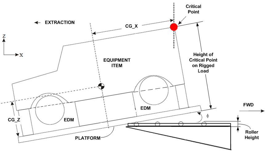
Dimensions – Height The height of the rigged air drop item is limited by the critical point during the tip-off phase of air drop (See Figure 2-1). The critical point is to adequately clear the surrounding aircraft structure during all phases of air drop transport. The height requirements of items 1.1.1 and 1.1.2 are also applicable. (Sourced from ASD-TM-77-1, August 1992, Paragraph 8)
|
In the first instance, the maximum allowable height of the rigged air drop load can be estimated using MIL-STD-1791D Ch1 Figures B-77 (C-17A aircraft) and B-103 (C-130J aircraft). The tip-off phase of air drop occurs once the centre of gravity of the rigged load passes over the edge of the aircraft ramp. This causes the rigged load to rotate as it exits the aircraft. The point most likely to strike the aircraft during rotation is the critical point. See Figure 2-1. As a guide, 5in is considered adequate clearance from the surrounding aircraft structure Load item designers should consider that the allowable height of the rigged air drop item includes several layers of Energy Dissipating Material and the Type V platform thickness (a typical estimate for this is 15in) placed beneath the load item. |
Analysis (required) and Test (required at AMTDU discretion) |
||||||||||||||||||||||||||||
|
Figure 2-1 – Tip-off phase during air drop |
|||||||||||||||||||||||||||||||
|
2.2.6 |
Dimensions – Length and Width The length and width of the air drop item are to conform to the selected platform dimensions published in 7279.001-1-2 Section 1 Chapter 6 and overhang requirements as published at AAP 7279.001-1-2 Section 1 Chapter 5. The length and width requirements of Item 1.1.1 are also applicable. (Sourced from ASD-TM-77-1, August 1992, Paragraphs 8 and 9) |
The dimensions of the rigged air drop loads are dependent on (but not limited to) impact mitigation design and parachute placement. AMTDU is responsible for ensuring this requirement is met. Nonetheless, awareness of this requirement is important during load item design to allow development of a suitable configuration. |
Analysis |
||||||||||||||||||||||||||||
|
2.2.7 |
Impact Survivability (Australian Supplement) Load items must be capable of sustaining minimum vertical deceleration forces (G loading) from Table 2-1 without any detrimental effect on the load item’s function or structure. Table 2-1 – Vertical deceleration acceleration factors (G loading) for load items to be air dropped
|
Flat contact surfaces of sufficient strength to support the impact loads on the underside of the load item (primary structure is ideal) will enable design of a successful energy dissipation system. Surfaces should also be evenly distributed about the load item’s centre of gravity. Load item designers are advised to consider this to facilitate a successful AD load certification On a typical configuration, the deceleration force of 20G will be met by using 3.1 square feet of energy dissipating crushing area for each 1000 pounds of item air drop weight and a total thickness of 12 inches of EDM composed of four layers of 3 inch thick panels; however, configuration will vary from item to item. AMTDU is responsible for the design of the Energy Dissipation System. The Energy Dissipation System typically consists of Energy Dissipating Material (EDM) placed underneath the load item, supported at primary structure components. |
Analysis, Test |
||||||||||||||||||||||||||||
|
2.2.8 |
Energy Dissipation System (Australian Supplement) Energy dissipation systems for air drop must be designed to support deceleration forces equivalent to the G loading forces in Table 2-1. |
Analysis or Test |
|||||||||||||||||||||||||||||
|
2.2.9 |
Restraint Load Factors The load item is to:
Table 2-2 – Restraint Load Factors for Air Drop (Adopted from AFIC AIR STD AM 4099)
|
When designing the load item, the designer is to consider the how the User will apply and achieve the required restraint. |
Analysis |
||||||||||||||||||||||||||||
|
2.2.10 |
Restraint of Secondary Cargo (Australian Supplement) The requirement specified by item 1.4.2 applies in conjunction with the applicable restraint load factors for Air Drop from Table 2-2. |
See guidance for Item 1.4.2. |
See Item 1.4.2 |
||||||||||||||||||||||||||||
|
2.2.11 |
Restraint Analysis for Air Drop Load items Restrained with Lashings (Australian Supplement) Item 1.4.3 applies to determining restraint of all air drop load items restrained using lashings. |
See guidance for Item 1.4.3 |
See Item 1.4.3 |
||||||||||||||||||||||||||||
|
2.2.12 |
Extraction Provisions – Item Extracted Loads The working limit load (or DLL) of the extraction provision is equal to aft load factor from Table 2-2 for item extracted loads multiplied by the rigged weight of the air drop item applied in the direction of extraction. The sustainable ultimate load is not to be less than 1.5 times the DLL. (Australian Supplement) Refer to MIL-STD-814D, Section 5, Clause 5.3.2.1 and 5.3.2.4 for extraction provisions dimensions and location, respectively. The general requirements of items 4.1.1 to 4.1.5 and 4.1.8 of this standard apply to extraction provisions.(Item 4.1.2 is an Australian Supplement) |
Item extraction is not the preferred method of extraction. The project is to request advice from AMTDU for the applicability of this method to the load item requiring certification. While MIL-STD-814 states that extraction provisions are to be positioned below the CG, extraction provisions should ideally be positioned as low as possible on the load item. |
Analysis orTest |
||||||||||||||||||||||||||||
| 2.2.13 |
Suspension Provisions – Item Suspended Loads Refer to MIL-STD-814D, Section 5, Clause 5.2 and 5.5.2 for strength and number of suspension provisions. Note: The definitions of Ultimate Load relative to DLL for this requirement differs to the Annex C Glossary definition. For this item 2.2.13 requirement, the definition provided at MIL-STD-814D, Clause 5.2.2 applies. |
The project is to request advice from AMTDU for the applicability of this method to the load item requiring certification. | Analysis or Test | ||||||||||||||||||||||||||||
Table 3 presents instructions and guidance for application of the Aerial Delivery standard for EL transport via rotary wing aircraft. Table 3 makes reference to United States and international standards (as cited by Section 5, Chapter 5, Paragraph 5.5) to establish the requirement with some Australian supplements (as cited by Section 5, Chapter 5, Paragraph 5.6). The Australian Air Publications are used for design data. Where the international standards refer to U.S. Army Soldier Systems Center, AMTDU is the applicable agency.
The following standards and publications contain the relevant requirements and design data, and is to be read in conjunction with this part:
Adopted Standards (as cited by Section 5, Chapter 5, Paragraph 5)
MIL-STD-913A – Requirements for the Certification of Sling Loaded Military Equipment for External Transportation
USA ARMDL Technical Report 72-36 Design Guide for Load Suspension Points, Slings and Aircraft Hard Points (July 1972)
AFIC AIR STD AM 4076 Technical Criteria for the Transport of Cargo by Helicopter
Design Data
AAP7210.021-9-4 Helicopter External Load Rigging Procedures.
Due to the nature of certification for EL, the application of the standard is not straightforward and some interpretation of the requirements in Table 3 will inevitably be required. Consequently, design organisations will need to seek advice from AMTDU. Where such advice is required, this is identified in the guidance column.
Table 3 – External Lift Transport Certification Requirements and Verification
|
Item |
Instruction for Application of Standard |
Guidance |
Verification |
||||||||||||||
|
Load Item Lifting Provisions |
|||||||||||||||||
|
3.1.1 |
Number Refer to MIL-STD-209K, Section 5, Clause 5.1.1. |
Load items that meet this requirement allows compatibility with current Aerial Delivery Equipment used for EL. |
Inspection |
||||||||||||||
|
3.1.2 |
Location Refer to MIL-STD-209K, Section 5, Clause 5.1.2.
Lifting Provisions should be reasonably symmetrical about the longitudinal and lateral axes passing through the load item’s Centre of Gravity (or Centre of Gravity range) as determined in its air transport configuration(s) noting that the requirement from 3.3.2 is to also be met.
|
Load items that meet this requirement will promote load stability and allows compatibility with current Aerial Delivery Equipment used for EL. Advice for dual point lift configurations, where deemed appropriate, should be sought from AMTDU on a case by case basis.
|
Analysis or Test |
||||||||||||||
|
3.1.3 |
Strength Lifting Provisions, load spreading devices (including those subject to compressive loads), interference points, connecting equipment structure and any load bearing components are to have sufficient strength to withstand the Helicopter Sling Load (HSL) design limit load (DLL) applied to the lifting provisions. The above listed components are to be capable of sustaining an ultimate load of not less than 1.5 times the HSL DLL. The HSL DLL is to be determined using the worst case loading condition which is defined by the largest product of the HSL materiel lift point load factor (determined IAW Appendix A of MIL-STD-209K) and sling leg tension.
In the early stages of load item design, where the sling configuration is not fully defined, the HSL DLL is to be determined IAW MIL-STD-209K Appendix B applied at all angles within the range defined in Figure 3-1 below (Australian Supplement).
In the early stages of load item design, where the sling configuration is not fully defined, the minimum strength of each Lifting Provision is to be at least equal to 30 percent of the total air transport weight multiplied by the HSL materiel lift point load factor. This force is to be applied at all angles within the range defined in Figure 3-2 below (Australian Supplement).
Once the slinging configuration is defined by AMTDU, the HSL DLL is to be determined using the sling leg tension obtained from the simulated trial (conducted as per Item 3.3.3). Note that the general requirements from items 4.1.1 to 4.1.8 apply to lifting provisions. (Item 4.1.2 is an Australian Supplement)
|
The project is to request advice from AMTDU if a dual point slinging configuration must be employed. Compliance to this requirement can only be fully achieved after consultation with AMTDU for an assessment of a suitable proposed slinging configuration. The load item weight used for analysis may be defined by an air transport weight in place of the GVM/Gross Weight. This configuration will need to be carefully considered and communicated to AMTDU. The worst case loading condition is the combination of material lift point load factor and air transport weight that produces the greatest HSL DLL. The worst case loading condition might not occur at the maximum air transport weight and consideration should be given to this to determine the HSL DLL. The load item air transport configuration(s) and CoG envelope should be determined prior to any analysis being carried out on the lift points. A shift in CoG position will affect the distribution of loads between sling legs. Changes to CoG location after the air transport configuration is provided to AMTDU is to be avoided as they may invalidate AMTDU load certification activities being conducted for the load item. Further, when defining an air transport configuration for the vehicle, the aircraft limitations (such as lifting capacity and payload/range) is to be considered. Where strength is determined by analysis, appropriate design factors are to be applied. For welded structures this is to include a weld capacity reduction factor as per Australian Standard AS4100 or equivalent international welding standards. Reduction and fitting factors for fasteners are to be used where applicable. Any structure where there are abrupt changes in geometry is to make allowance for appropriate stress concentration factors in the analysis. |
Analysis and Test |
||||||||||||||
|
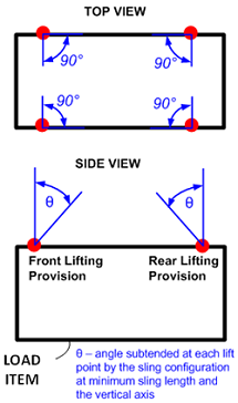
Figure 3-1 – Required angle range for the HSL DLL for single point lifting configuration |
Figure 3-2 – Required angle range for the HSL DLL for dual point lifting configuration |
||||||||||||||||
|
3.1.4 |
Dimensions Refer to MIL-STD-209K, Section 4, Clause 4.11. |
No guarantee of provision strength results from conformity to this requirement (see Item 3.1.3 for strength requirement). |
Inspection |
||||||||||||||
|
3.1.5 |
Frame Members Refer to MIL-STD-913A, Section 4, Clause 4.1.4 noting that Items 3.1.1 – 3.1.4 apply to frame members (Item 3.1.3 is an Australian Supplement). |
See glossary for a definition of Frame Members. |
See 3.1.1 – 3.1.4 (i) Inspection (ii) |
||||||||||||||
|
3.1.6 |
Spreader Bars Where spreader bars are approved for use, refer to MIL-STD-913A, Section 4, Clause 4.1.5. Spreader bars or cable guides are to be used during sling configuration testing and are to withstand all sling leg forces imposed noting the ultimate load requirement from Item 3.1.3 also applies. (Item 3.1.3 is an Australian Supplement)
|
Spreader bars are considered a deviation and AMTDU is to be consulted if their use is intended for EL of load items. Where used, it is strongly advised that spreader bars be part of the complete equipment schedule Spreader bars are means for altering the sling leg angles to achieve the minimum sling leg clearance specified at Item 3.2.1. Designers should consider using cable guides or reinforcement of sling contact points on the load item as an alternative to requiring spreader bars. Cable guides may be used as an alternative to spreader bars. Refer to Item 3.1.4 for appropriate minimum diameter (Dmin) dimension of cable guide openings for sling compatibility. |
Inspection and Analysis or Test |
||||||||||||||
|
3.1.7 |
Applicability of General Requirements The general requirements detailed under items 4.1.1 to 4.1.8 apply to Lifting Provisions. (Item 4.1.2 is an Australian Supplement) |
See guidance for items 4.1.1 to 4.1.8. |
See items 4.1.1 to 4.1.8 |
||||||||||||||
|
Load Item Physical Properties |
|||||||||||||||||
|
3.2.1 |
Load Item Basic Data The load item designer or Project office is to provide the following Basic Data for the load item as listed by USA ARMDL Technical Report TR 72-36 (Jul 72), Page 1 (republished as follows):
|
The load item designer should endeavour to position the load item centre of gravity forward of its centre of pressure. The desired centre of gravity position should be a point at which not more than one third of the total surface area is located forward of the centre of gravity. This greatly improves the likelihood of achieving stability during EL. Methods to alter the Centre of Gravity and centre of pressure are available in AMTDU EL designs; however, these methods are not to be relied upon due to significant operational implications. The asymmetry ratio (Item 3.3.2) is to be considered in conjunction with this requirement as it may constrain the centre of gravity position relative to the centre of pressure. |
Inspection |
||||||||||||||
|
Requirements for Sling Configuration |
|||||||||||||||||
|
3.3.1 |
Minimum Sling Leg Clearance Refer to MIL-STD-913A, Section 4, Clause 4.2.2. This clause applies to all sling types including textile/webbing slings and chain leg slings. |
To define a lifting configuration, at a minimum, the following are to be specified:
Part of determining a suitable sling configuration initially involves selection of single point, dual point or tandem lifting configurations. Single point lift with four lifting provisions is typically adopted for most EL load items. If dual or tandem lifting configurations are being sought, AMTDU is to be contacted in the first instance. |
Inspection or Demonstration |
||||||||||||||
|
3.3.2 |
Asymmetry of Lifting Provisions The ratio of the largest vertical sling force to the smallest vertical sling force is not to exceed 1.2 (requirement republished from USA ARMDL Technical Report TR 72-36 (Jul 72), Pages 2 and 21)
|
Analysis or Test |
|||||||||||||||
|
3.3.3 |
Simulated Trial – External Lift (Static Lift Testing) Static lift testing for each proposed lifting configuration is to meet the requirements of MIL-STD-913A, Section 5, Clause 5.1 with the following exception:
|
AMTDU is responsible for certifying the compliance of a load item in its EL configuration to this requirement. Nonetheless, this requirement should be considered during load item design to facilitate successful EL certification of the load item. |
Analysis and Test |
||||||||||||||
|
3.3.4 |
Load in-flight stability The load item is to be lifted in-flight beneath applicable rotary wing aircraft in its proposed air transport configuration(s) to determine load in-flight stability. Refer to Clause 5.3b-c MIL-STD-913A for the required test outcomes. |
Consideration is to be given to test the worst case air transport configuration(s). Guidance provided at Item 3.1.3 for the worst case loading configuration is applicable to this requirement. AMTDU is responsible for certifying the compliance of a load item in its EL configuration to these design requirements. To facilitate successful EL certification of the load item, these requirements are to be considered during load item design. |
Test |
||||||||||||||
|
Secondary Cargo |
|||||||||||||||||
|
3.4.1 |
Restraint of Secondary Cargo (Australian Supplement) Secondary cargo carried by the underslung primary cargo item, is to be restrained to the cargo restraint load factors from Table 3-1. Table 3-1 – Secondary Cargo Restraint Load Factors for EL
Loose items of low mass (an individual item weighing less than 50lb) are not subject to the above restraint requirement, however, are to be securely restrained to prevent them from becoming a hazard. Where secondary cargo restrained using lashings, refer to Item 1.4.3 for determining the available restraint. |
For this requirement, secondary cargo refers to any item physically connected to the primary load item during external lift such as internal items, external items, auxiliary equipment and integral equipment. This can include (but is not limited to) cargo carried by vehicle/trailers, internal cargo within a containing device, purpose built mission modules and integral items such as jerry cans, fire extinguishers spare wheels carried using purpose built provisions.
|
Analysis |
||||||||||||||
Table 4 presents instructions and guidance for application of the Aerial Delivery standard for attachment points, lifting provisions and/or secondary cargo tie down provisions fitted to a load item to be certified for AL, AD and/or EL. Table 4 makes reference to the adopted United States standard (as cited by Section 5, Chapter 5, Paragraph 5.5) to establish the requirement and also contains Australian supplements (as cited bySection 5, Chapter 5, Paragraph 5.6). Where the international standards refer to a US agency (such as Air Transport Test Loading Activity, U.S. Army Soldier Systems Center, US Army SDDCTEA), AMTDU is the applicable agency
The requirements in referenced by this part are military unique interface requirements developed specifically for ensuring that the attachment points and/or lifting provisions on military equipment (load items) meet the physical, functional and operational environment attributes for ADF aircraft.
The US Standard, MIL-STD-209K Lifting and Tie-Down Provisions, contains the relevant requirements and is to be read in conjunction with this part.
Table 4 – Attachment Points, Lifting Provisions and, Secondary Cargo Tie Down Provisions Certification Requirements and Verification
|
Item |
Requirement |
Guidance |
Verification |
|
General |
|||
|
4.1.1 |
Surface of Provisions Refer to MIL-STD-209K, Section 4, Clause 4.2. |
Load items meeting this requirement allow compatibility with current Aerial Delivery Equipment. |
Inspection |
|
4.1.2 |
Shackles Refer to MIL-STD-209K, Section 4, Clause 4.3 with the following additions:
|
This requirement simplifies the air transport configuration of the load item by ensuring shackles always remain with the load item being transported.
|
Analysis or Test |
|
4.1.3 |
Hub and Axle Requirements The use of wheel hubs and axles for restraint are prohibited IAW the requirements of MIL-STD-209K, Section 4, Clause 4.4. |
Wheel hubs and axles are considered primary structure but this does not guarantee their suitability for lifting or restraint. Designers are to always install designated attachment points and/or lifting provisions to load items. |
Inspection |
|
4.1.4 |
Removable Provisions Removable attachment points and lifting provisions are prohibited IAW the requirements of MIL-STD-209K, Section 4, Clause 4.5. |
Load items meeting these requirements simplify and ensures consistency of the air transport configuration of the load item. AMTDU is to be consulted if these requirements cannot be met. |
Inspection |
|
4.1.5 |
Freezing and Jamming Refer to MIL-STD-209K, Section 4, Clause 4.6. |
Inspection or Demonstration |
|
|
4.1.6 |
Stowable Lifting Provisions Where the load item contains stowable lifting provisions, refer to MIL-STD-209K, Clause 4.7. |
Demonstration |
|
|
4.1.7 |
Provision Dimensions Refer to MIL-STD-209K, Section 4, Clause 4.11. The option presented by MIL-STD-209K, Clause 5.2.3.1 may be utilised for load items weighing 50,000lb or more. If used, refer to MIL-STD-209K, Clause 5.2.4. |
Load items meeting this requirement allow compatibility with current Aerial Delivery Equipment. There is no guarantee of provision strength that results from conformance to this requirement. Refer to strength requirements for each attachment point or lifting provision. |
Inspection |
|
4.1.8 |
Marking/Identification The load item is to be furnished with a shipping data plate as per MIL-STD-209K, Clause 5.7.1. At a minimum, the shipping data plate is to provide the:
All attachment points and lifting provisions are to be identified as per MIL-STD-209K, Clause 5.7.2. The shipping data plate is to be updated to incorporate configuration changes made to the load item. |
|
Inspection |
|
Secondary Cargo Tie down Provisions - The requirements listed under this clause are applicable to load items with a designated cargo area. Note: the requirements listed below are applicable only to ‘secondary cargo tie down provisions’ which are not included under ‘attachment points’ (see the Annex C Glossary for further clarification). |
|||
|
4.2.1 |
Number Refer to MIL-STD-209K, Clause 5.4.1.
|
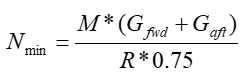
The intent of this requirement is to ensure that all payloads are restrained to the required inflight load or restraint factors. The following calculation is recommended to determine if sufficient cargo tie down provisions exist for the load item payload mass to be adequately restrained. The value determined is rounded up to the nearest even number:
Where this formula results in a value less than four, the minimum number of cargo tie down provisions is four. Nmin – Minimum number of cargo tie down provisions M – Load item mass in air transport configuration Gfwd, Gaf – The applicable restraint load factor in the forward and aft directions (items 1.4.1 or 2.2.9) R – Strength Rating of attachment point as per Item 4.2.3 |
Analysis |
|
4.2.2 |
Location Refer to MIL-STD-209K, Clause 5.4.2.
|
Secondary Cargo tie down provisions are to be positioned symmetrically around the cargo area, such that cargo can be restrained to satisfy Items 1.4.1 (AL), 2.2.9 (AD), or 3.4.1 (EL) as applicable to the required transport method. Secondary cargo tie down provisions are usually best positioned around the perimeter of the cargo area. The designer is to consider the intended use of the cargo area and types of cargo in the air transport configuration when deciding on the provision location, as this may dictate that provisions be placed in other locations (e.g. centreline, gird pattern, column arrangement). |
Inspection |
|
4.2.3 |
Strength Refer to MIL-STD-209K, Clause 5.4.3 for the strength of secondary cargo tie down provisions.
For AL load items, the strength rating is to consider yield and ultimate factors consistent with the requirements of Item 1.4.1.
For AD and EL load items, the strength rating is the allowable Design Limit Load. In addition secondary cargo tie down provisions are to be capable of sustaining an ultimate load of not less than 1.5 times the Design Limit Load. (Australian Supplement – AD only).
|
|
Analysis or Test |
|
4.2.4 |
Dimensions Refer to MIL-STD-209K, Clause 5.4.4 for the dimensions of secondary cargo tie down provisions.
For cargo areas with a capacity greater than 5000lb, refer to MIL-STD-209K, Clause 5.5.4.
|
A load item that meets this requirement enables compatibility with current Aerial Delivery Equipment. There is no guarantee of provision strength that results from conformance to this requirement. See Item 4.2.3 for the strength requirement of secondary cargo tie down provisions. |
Inspection |
|
4.2.5 |
Directional Capabilities Refer to MIL-STD-209K, Clause 5.4.6 for the directional capabilities of secondary cargo tie down provisions.
|
|
Inspection |
Table 5 presents instructions and guidance for application of the Aerial Delivery standard for attachment points fitted to a load item to be certified for AL and AD. Table 5 makes reference to a United States standard (as cited by Section 5, Chapter 5, Paragraph 5.5) to establish the requirement and also contains Australian supplements (as cited bySection 5, Chapter 5, Paragraph 5.6). Where the international standards refer to a US agency (such as Air Transport Test Loading Activity, U.S. Army Soldier Systems Center, US Army SDDCTEA), AMTDU is the applicable agency
US standards use the terms ‘tie down provisions’ and ‘supplementary tie down’ provisions. This Annex does not differentiate between the two terms and uses the term ‘Attachment Point’ to include both ‘tie down provisions’ and ‘supplementary tie down’ provisions. See the Annex C Glossary for a definition of all terms.
The US Standard, MIL-STD-209K Lifting and Tie-Down Provisions, contains the relevant requirements and is to be read in conjunction with this part.
Table 5 – Attachment Points Certification Requirements and Verification
|
Item |
Requirement |
Guidance |
Verification |
||||||||||||||
|
5.1.1 |
Restraint of Item Refer to MIL-STD-209K, Clause 4.1. |
|
Inspection |
||||||||||||||
|
5.1.2 |
Number (Australian Supplement) The minimum number of attachment points fitted to the load item is to conform to the value determined by the formula below. The value determined is rounded up to the nearest even number:
Where this formula results in a value less than four, the minimum number of attachment points is four. Nmin – Minimum number of attachment points M – Load item mass in air transport configuration Gfwd, Gaft – The applicable restraint load factor in the forward and aft directions (items 1.4.1 or 2.2.9) R – Strength Rating of attachment point as per Item 5.1.3 |
Load items meeting this requirement allow for the successful design of a restraint pattern for AL and/or AD modes of transport.
|
Analysis |
||||||||||||||
|
5.1.3 |
Strength Rating (Australian Supplement) The magnitude of the strength rating of the attachment points is to be 5000lbf (applicable to AL only), 6000lbf (applicable to AD only), 10,000lbf, 20,000lbf, 25,000lbf or 50 000lbf (AL & AD).
For AL load items, the strength rating is to consider yield and ultimate factors consistent with the requirements of Item 1.4.1.
For AD load items, the strength rating is the allowable Design Limit Load. In addition attachment points are to be capable of sustaining an ultimate load of not less than 1.5 times the Design Limit Load.
The strength rating is to:
|
The listed rating magnitudes are determined from the rated strengths of the types of lashings used on board ADF aircraft. AMTDU is to be consulted if the selected attachment point rating value varies from the provided values. It may be beneficial to ensure front and rear placed attachment points are of whole multiples of the below strengths to allow fitment of multiple lashings. As a guide, the following table may used to select a suitable target attachment point strength rating based on load item weight: Table 5-1 – Suggested attachment point strength rating for a given load item weight
When qualifying the strength of the attachment point, the designer is to make allowances for the physical and chemical properties of the material (e.g. fatigue, corrosion, galvanic action and harsh environments) and for normal wear and tear during the expected life of the load item. The following should be considered during any analysis or testing conducted for a strength rating:
Where strength is determined by analysis, appropriate design factors are to be applied. For welded structures this is to include a weld capacity reduction factor as per Australian Standard AS4100 or equivalent international welding standards. Reduction and fitting factors for fasteners are to be used where applicable. Any structure where there are abrupt changes in geometry is to make allowance for appropriate stress concentration factors in the analysis. |
Analysis or Test |
||||||||||||||
|
5.1.4 |
Location Refer to MIL-STD-209K, Clause 5.2.2.
|
MIL-STD-209K, Clause 5.2.2c is to ensure maximum accessibility to facilitate application of lashings at equal lengths and angles. MIL-STD-209K, Clause 5.2.2e is to ensure access to APs as well as ensure sufficient vertical restraint can be achieved with the designed APs. |
Inspection |